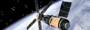
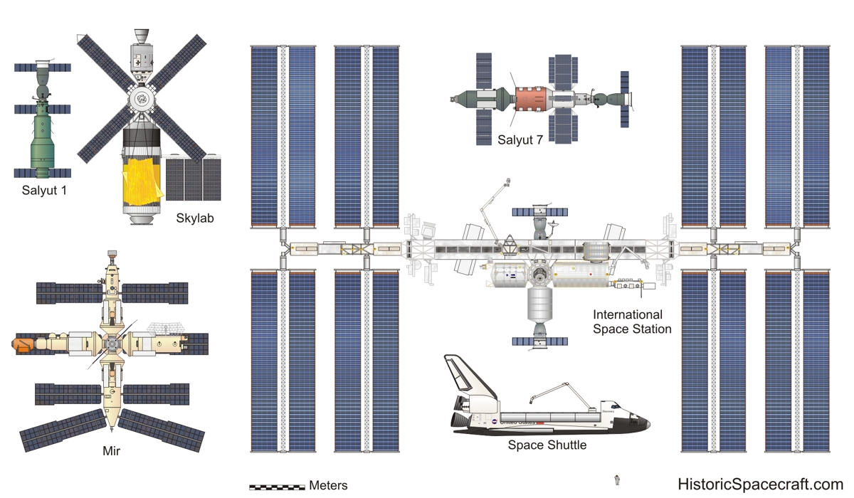
America's First Space Station
Early Plans (Wet or Dry?)
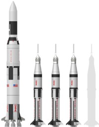
In the 1960's NASA investigated ways to gain further spaceflight experience after the Apollo Lunar missions. Some plans involved launching a space station, or orbital workshop as it became known, on two-stage, Saturn IB rockets.
The hydrogen tank of the Saturn S-IVB stage offered ample room for setting up an orbital workshop. Early plans involved what would be known as the "wet" workshop. Launched full of liquid oxygen and liquid hydrogen, the S-IVB would function normally as the rockets second stage during ascent. Most of the fuel would be consumed as the J-2 engine propelled the stage into orbit. Once safely in orbit, remaining fuel and oxidizer could be vented into space, allowing the hydrogen tank to later be pressurized with a breathable atmosphere and occupied by astronauts. Special fittings would be attached to the walls allowing equipment and experiments to be mounted when astronauts arrived. Floors and walls, formed by an aluminum grid structure, with ample openings so as not to interfere with fuel flow, could be pre-installed in the tank.
On top of the S-IVB stage would be a Multiple Docking Adaptor, or MDA. The MDA would have up to five docking ports for Apollo spacecraft or expansion modules. The MDA would contain many pieces of equipment that would be installed within the vented hydrogen tank when astronauts arrived.
Concerns existed about the length of time needed for astronauts, working in zero-g, to unpack large amounts of equipment launched in the MDA, transfer it into the workshop, and install it.
In 1969, it became apparent that several Saturn 5 rockets, already purchased, would remain unused after the Apollo Lunar missions. A decision was made to switch the Skylab launch from the smaller Saturn IB rocket to the much more capable Saturn 5 rocket. The greater capacity of the larger rocket meant that the S-IVB stage would not need to function as a rocket stage during launch. The "dry" workshop, as it became known, would be fully equipped on the ground. There was even enough capacity to launch the Apollo Telescope Mount on the same rocket. Earlier plans had the telescope mount launching separately and docking with the workshop.
Disaster on Launch Day
The Skylab space station was launched on 14 May 1973. Shortly after liftoff, a large micrometeoroid shield, designed to protect the orbital workshop, started to structurally fail. Within seconds, aerodynamic forces stripped the shield completely free from the station. As the shield tore off, one of two main solar array wings, designed to deploy only in the vacuum of space, partially deployed. Several minutes later, after the second stage finished its burn, retro rockets fired to separate the booster from the station. Exhaust from these retro rockets impacted the partially deployed solar array and ripped it from the station.
Once in orbit, more problems soon became apparent. Not only had the micrometeoroid shield and one solar wing been completely torn off, but the opposite array, while still attached to the station, had been tangled in debris and failed to deploy.
The situation continued to worsen. The missing micrometeoroid shield exposed the station to higher levels of solar heating then it was designed for. Temperatures in the station rose to 126 deg F (52 deg C).
Rescue and Repair
Fortunately, the four solar arrays on the Apollo Telescope Mount (ATM) deployed as planned. This power allowed controllers to operate the station, at least at a minimum level, until repairs could be made.
The first Skylab crew, scheduled to lift off the day following Skylab's launch, was delayed while tools and techniques were quickly developed to repair the crippled station.
On 25 May 1973, the first Skylab crew, led by veteran astronaut Charles Conrad, lifted off from Kennedy Space Center. They carried with them several solar shades, designed to shade the orbital workshop, and a variety of cutters and other tools designed to free the jammed solar array.
With an internal temperature well over 100 degrees Fahrenheit, astronauts could initially spend only short periods of time in the station. On their second day in orbit, the crew was able to deploy a solar shade, known as the 'parasol'. The parasol was deployed through an airlock in the side of the orbital workshop. The 22ft by 24ft parasol, composed of woven nylon, mylar, and aluminum, reflected enough solar energy to lower the internal temperatures to tolerable levels.
The first attempt to free the jammed solar array failed. A second attempt, on June 7, successfully released the solar panel. The station now had twice as much power available.
Despite the added workload required to repair the station, the crew was able to complete nearly all planned scientific objectives.
Skylab's Legacy
Skylab was ultimately visited by three crews. Each crew, consisting of a commander, a pilot, and a science pilot, was transported to the station using Apollo spacecraft, launched on Saturn IB rockets. Each successive crew stayed longer then the previous mission. Durations of 28 days, 59 days, and 84 days were achieved.
On 11 July 1979, Skylab re-entered Earth's atmosphere. Debris from the station fell over the Indian ocean and parts of Australia.
Despite nearly catastrophic problems early on, Skylab proved highly successful and completed all of its major objectives. Proving that humans could do productive work for prolonged periods of time while in orbit.
Skylab Components
Position mouse pointer over listed items to see their location. Click links for more information.
Apollo Telescope Mount (ATM)
Designed to support solar observations, the Apollo Telescope Mount (ATM) housed a number of solar telescopes. The ATM consisted of an octagonal structure 3.4m in diameter, and 4.4m long. Inside was a cylinder, 2.1m in diameter and 3m long. A cruciform structure, dividing the cylinder into four quadrants, provided mounting points for solar experiments housed within the cylinder. The inner structure was gimbaled, allowing very fine pointing control for the sensitive instruments. When not in use, each instrument was protected by a moveable aperture door.
Attached to the ATM were three gyros. Known as control moment gyros (CMG), these units helped stabilize the Skylab station.
The ATM also included four solar arrays. The solar arrays proved critical to the success of the space station after one of the main solar panels was ripped away during launch.
To fit within the payload shroud during launch, the ATM was initially positioned in-line with the MDA and orbital workshop. Once the shroud was jettisoned, and the station was in orbit, the ATM was rotated 90 degrees to assume its operational position.
Solar experiments mounted in the ATM included the following:
S-056 X-Ray telescope
S-054 X-Ray telescope
S-082A Extreme Ultraviolet Spectroheliograph
S-082B Ultraviolet Spectrograph
S-020 X-ray and extreme ultraviolet camera
S-055 Ultraviolet Spectroheliometer
S-052 White Light Coronagraph
H-alpha no. 1 Hydrogen-Alpha Telescope
H-alpha no. 2 Hydrogen-Alpha Telescope
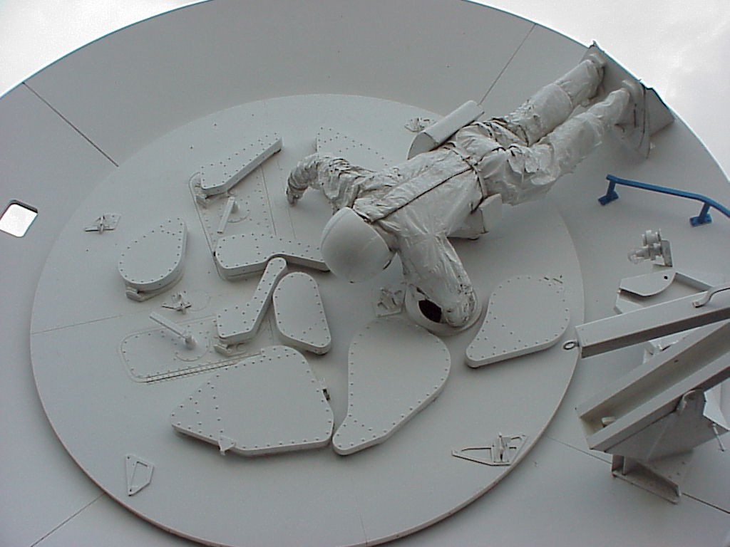
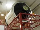
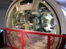
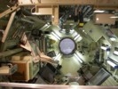
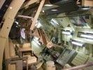
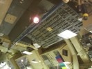
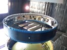
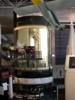
Apollo Telescope Mount Mockup
Skylab Apollo Telescope Mount mockup on display at the United States Space and Rocket Center. This hardware was used for training in the Neutral Buoyancy Laboratory. (Photos: Kevin Reynolds, 2001)
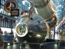
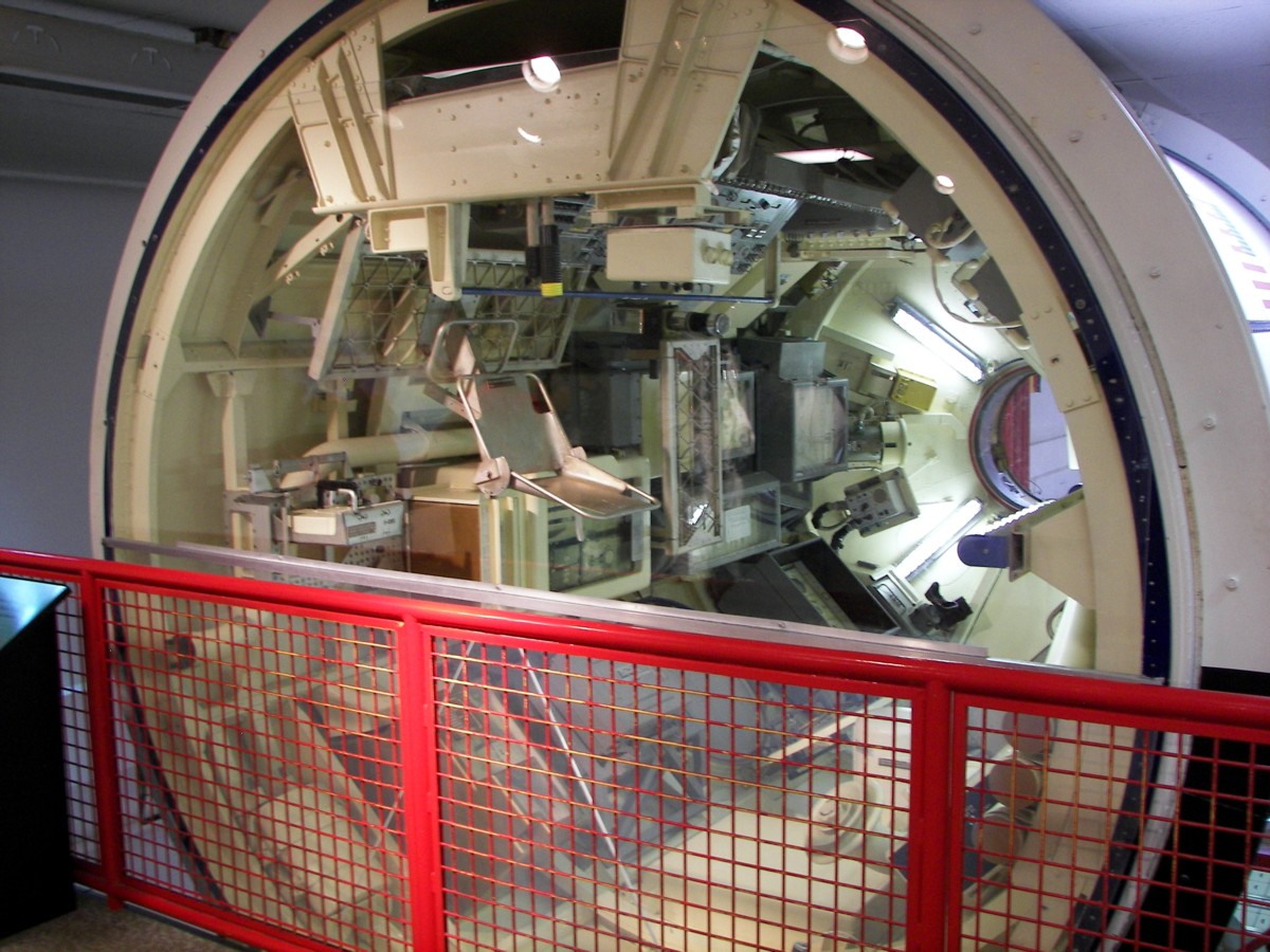
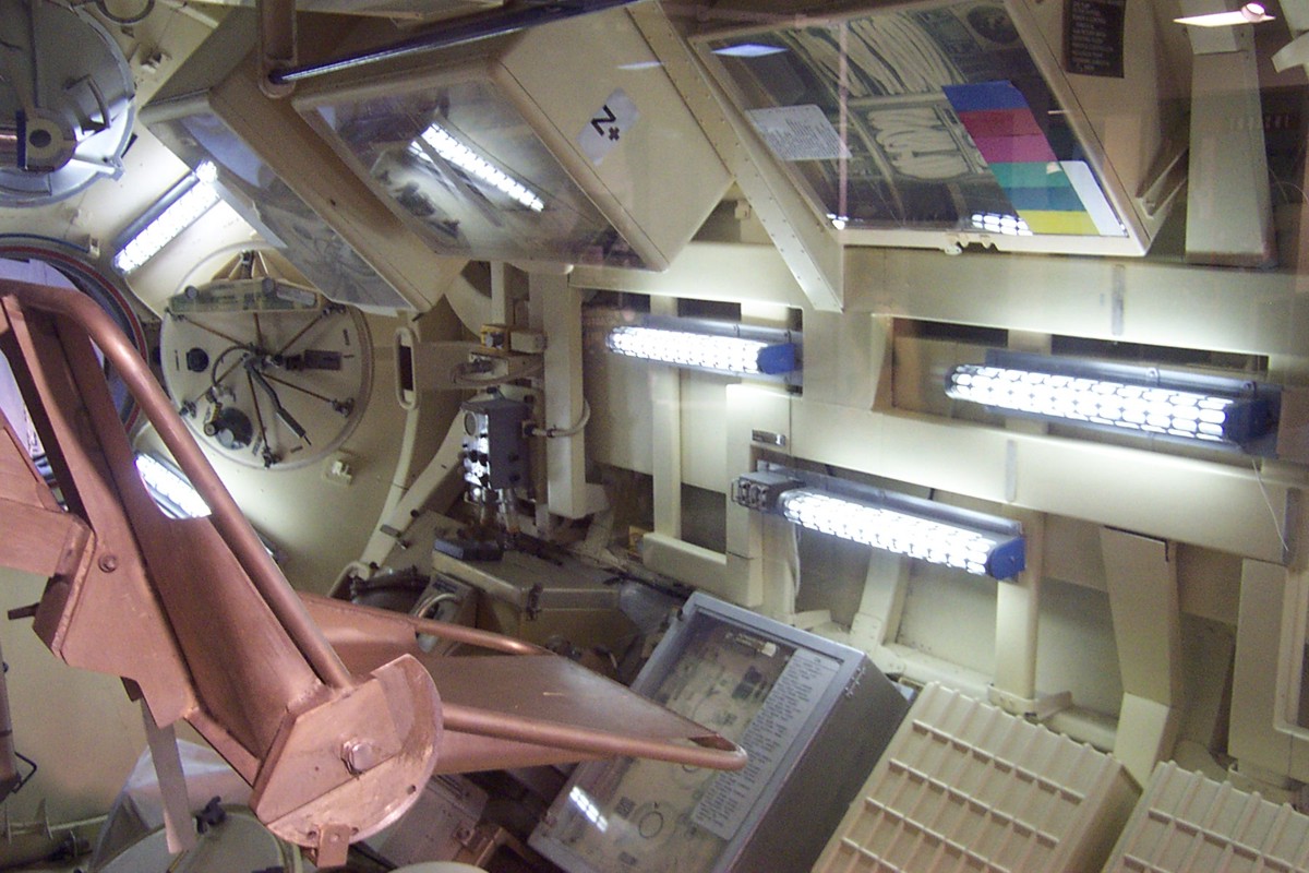
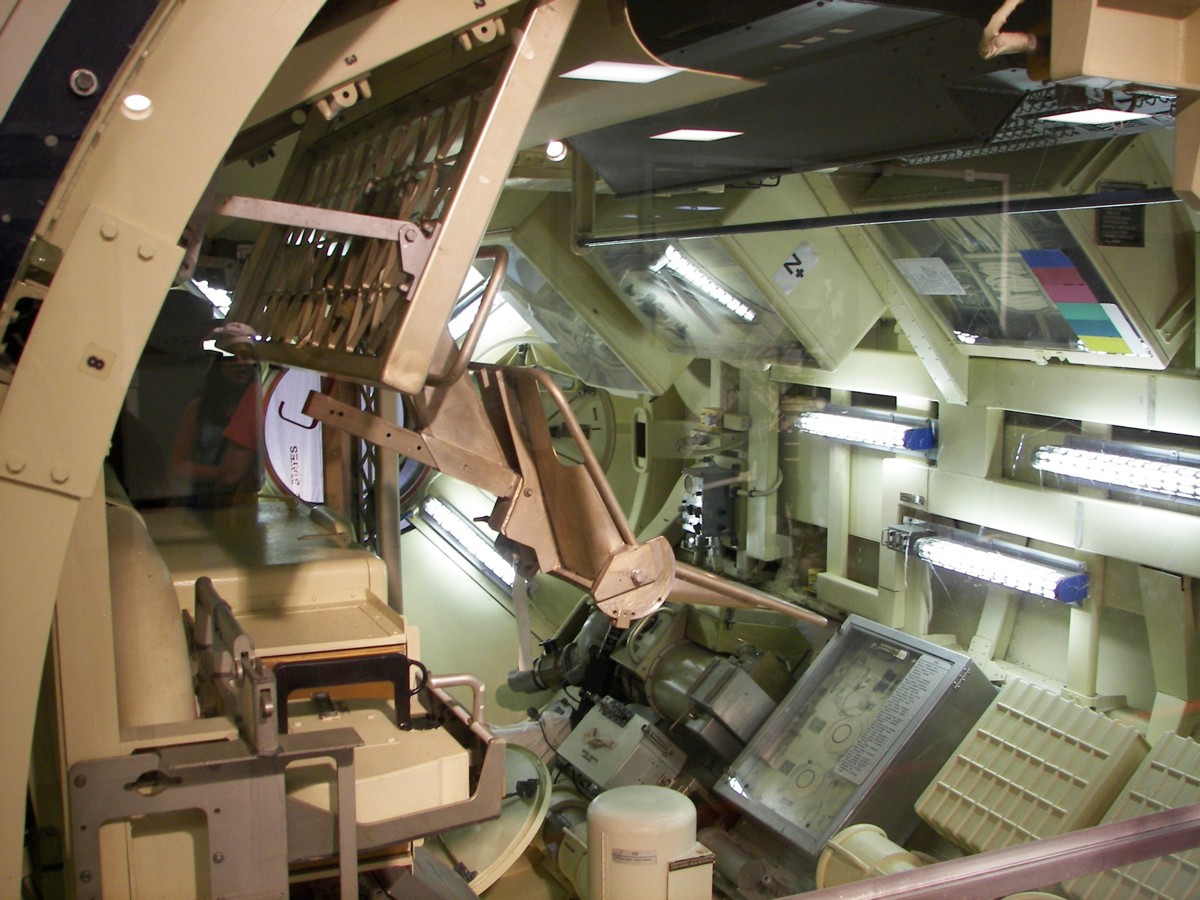
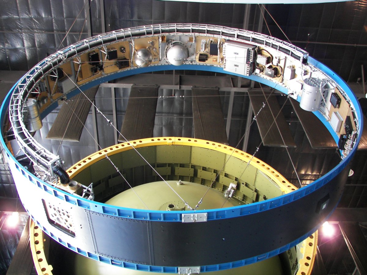
Multiple Docking Adaptor (MDA)
The MDA had two docking ports. The axial docking port, located on the end of the MDA, was the primary docking port for Apollo spacecraft. A radial docking port, located on the side of the module, served as a backup.
Control panels for the Apollo Telescope Mount, as well as several Earth resource experiments, were located in the MDA.
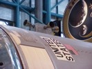
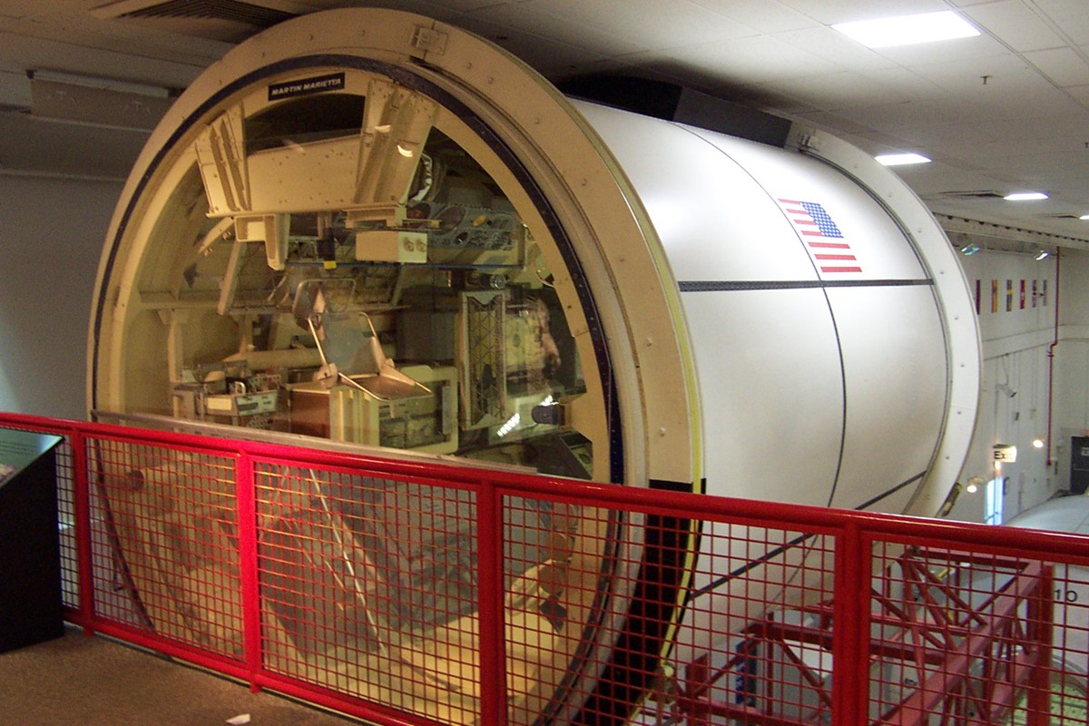
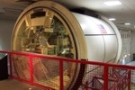
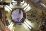
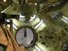
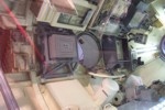
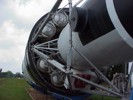
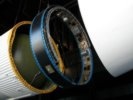
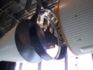
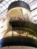
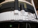
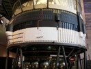
Multiple Docking Adaptor Trainer
Skylab Multiple Docking Adaptor on display at the Kennedy Space Center.(Photos: Richard Kruse, 2009)
Structural Transition Section (STS)
The Structural Transition Section, or STS, connected the Multiple Docking Adaptor and the Airlock Module.

Airlock Module (AM)
Located between the Multiple Docking Adaptor and the Orbital Workshop, the Airlock Module was designed to support EVAs from the Skylab space station. The module could be sealed off from the rest of the station and depressurized. A large EVA hatch, based on the hatches used on Gemini spacecraft, was mounted on the side of the module.
Each Skylab crew conducted several spacewalks. Objectives included changing film in the ATM, performing maintenance, and conducting experiments.
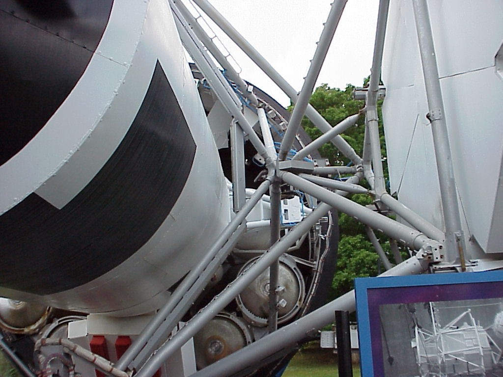
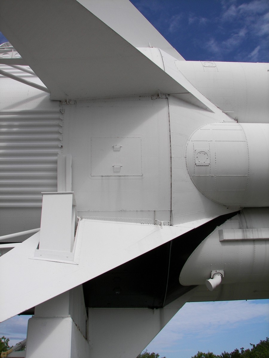
Fixed Airlock Shroud (FAS)
The Fixed Airlock Shroud, or FAS, was mounted forward of the Instrument Unit. The Airlock Module passed through the center of the FAS. The space between the FAS outer shell and the Airlock Module contained large, high pressure oxygen tanks, nitrogen tanks, battery banks, and other equipment necessary for the station.
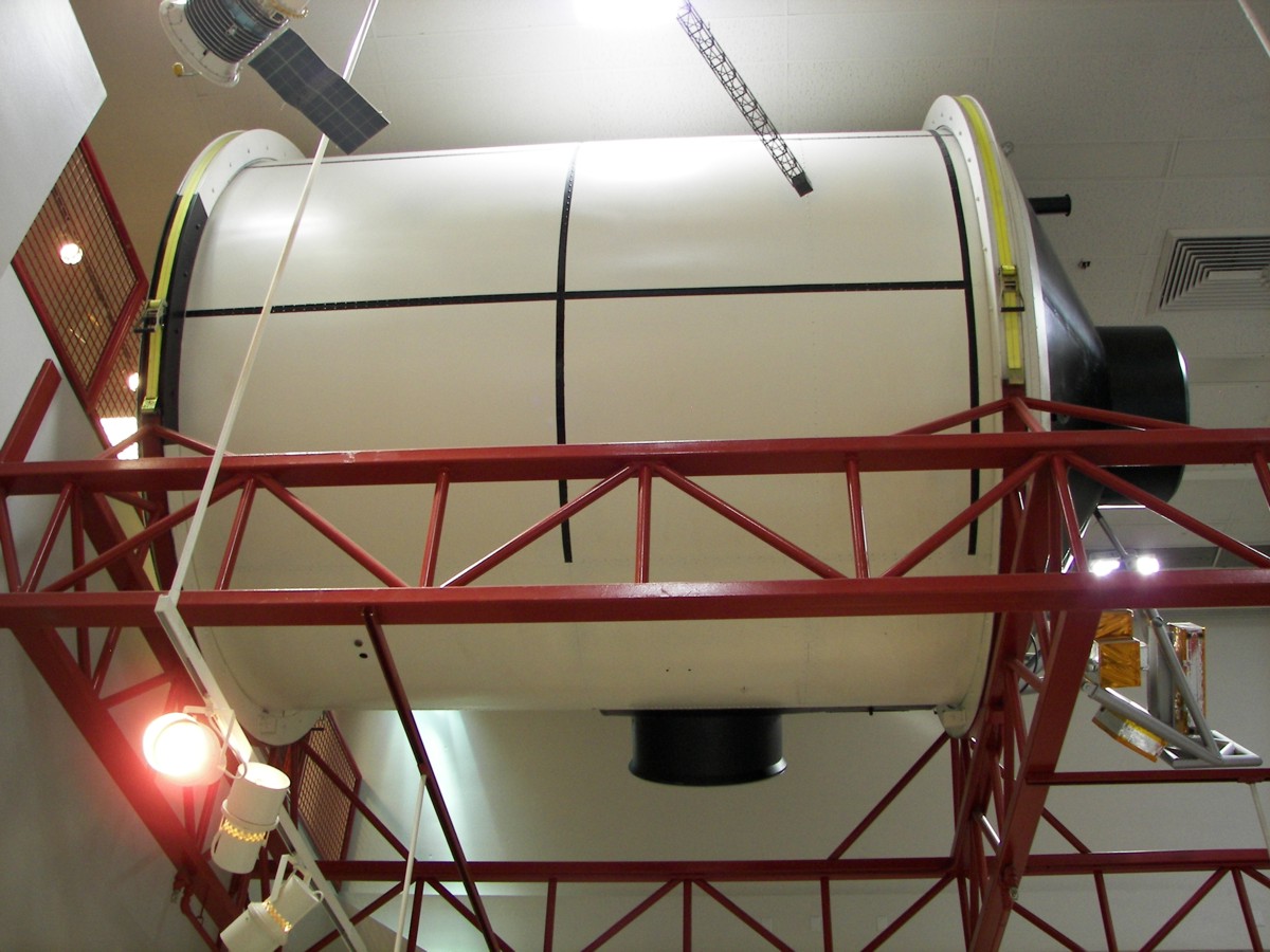
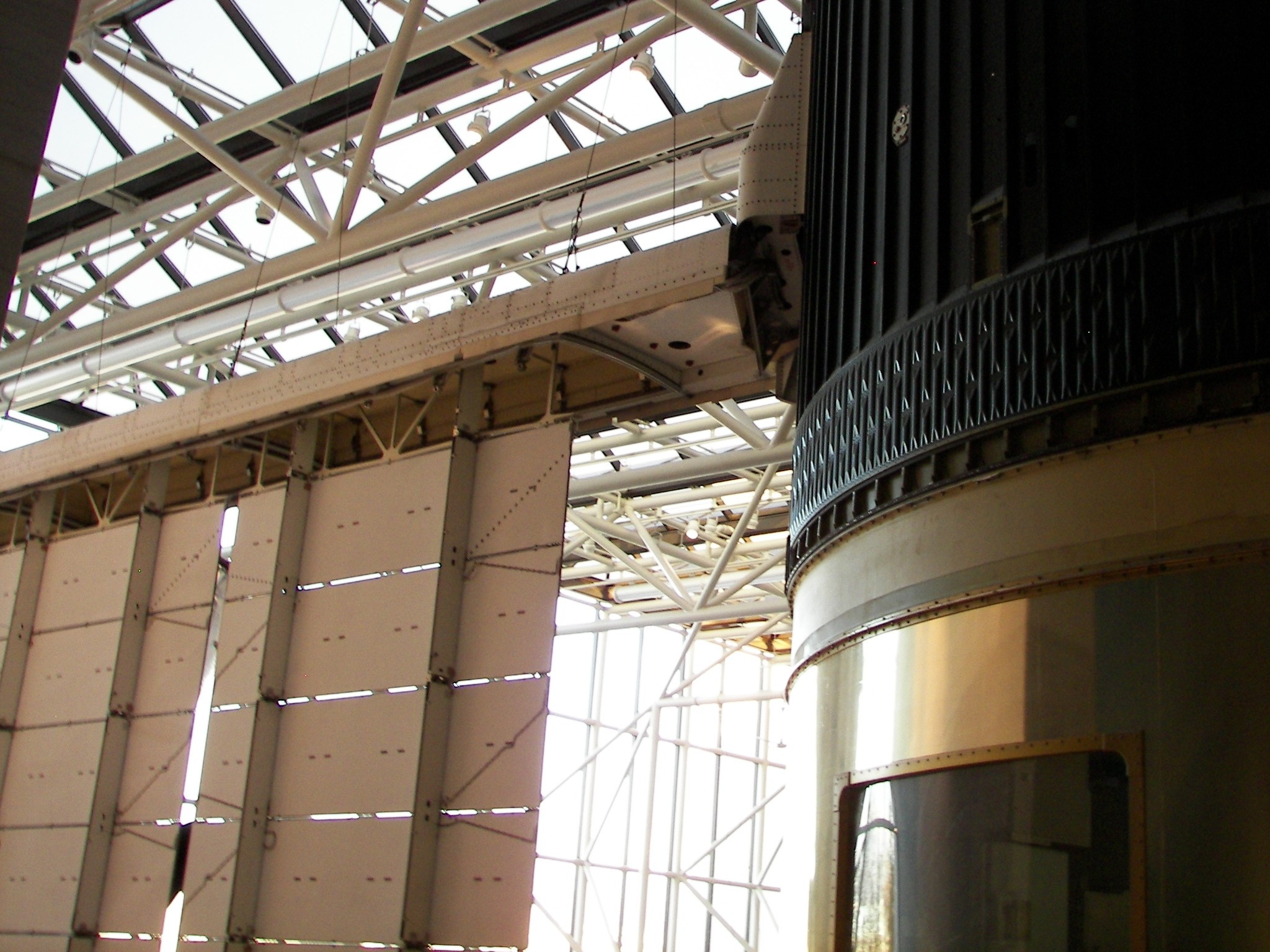
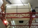
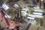
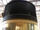
Skylab Mockup
Skylab mockup on display at the United States Space and Rocket Center. These photos show the Fixed Airlock Shroud area. Part of the Multiple Docking Adaptor can be seen in the foreground. (Photos: Kevin Reynolds, 2001)
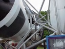
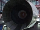
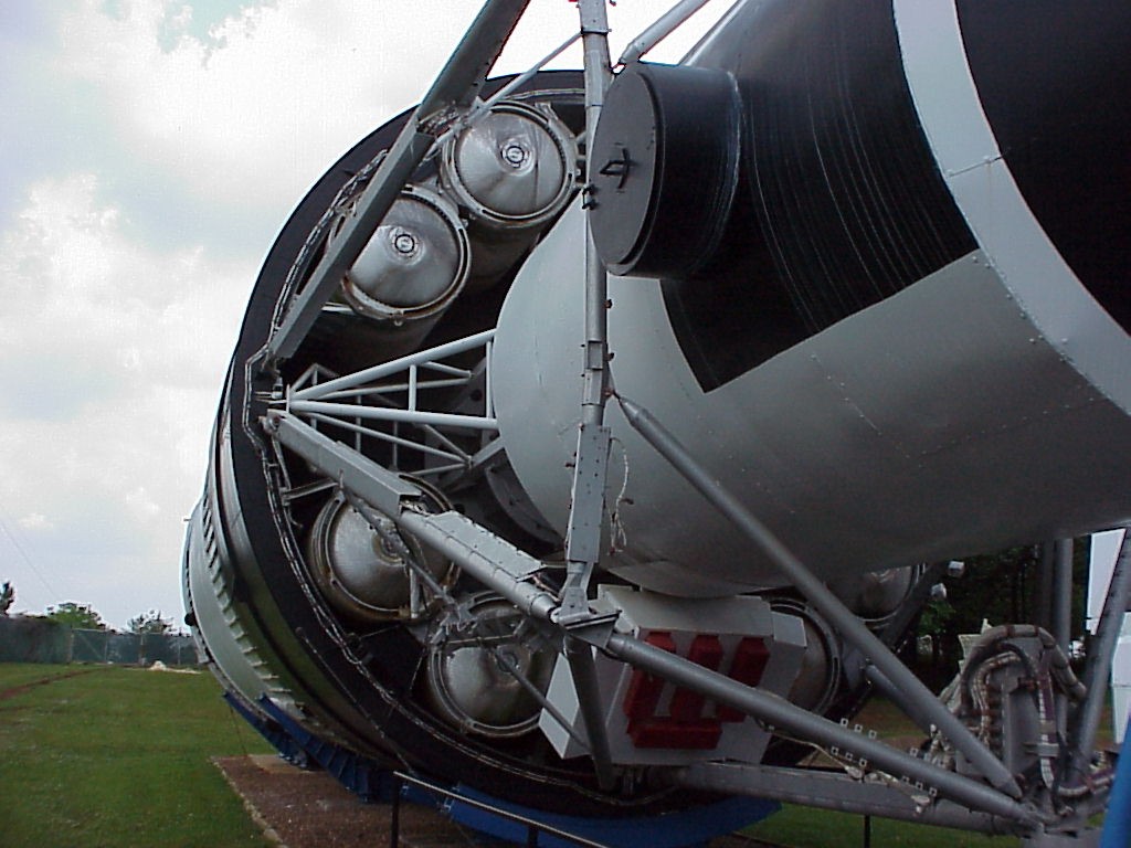
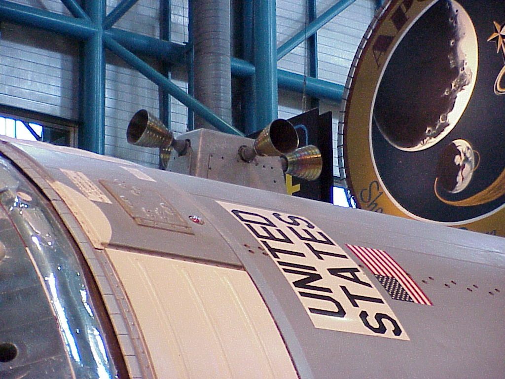
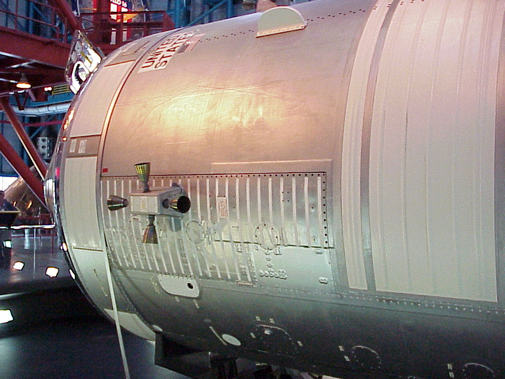
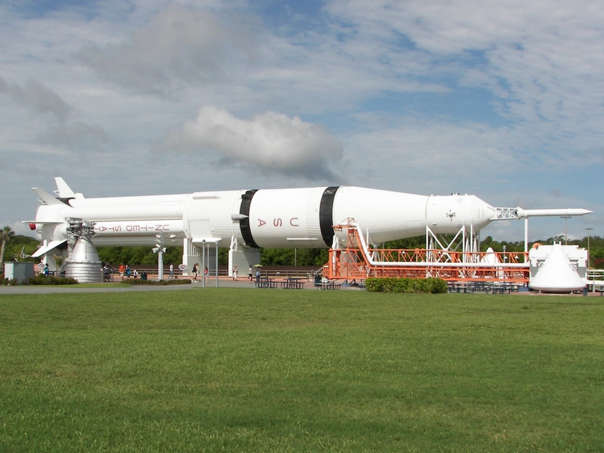
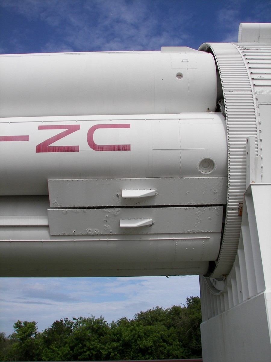
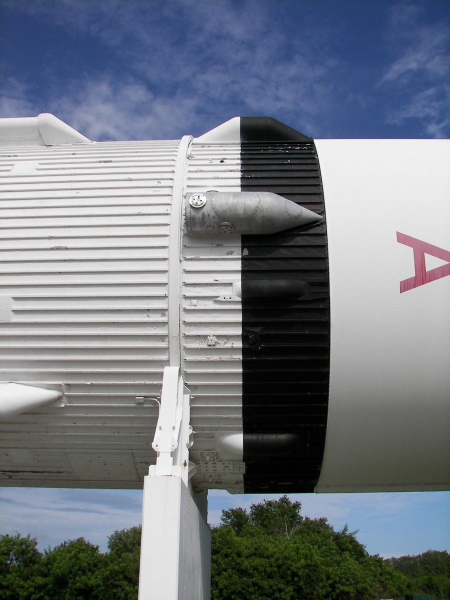
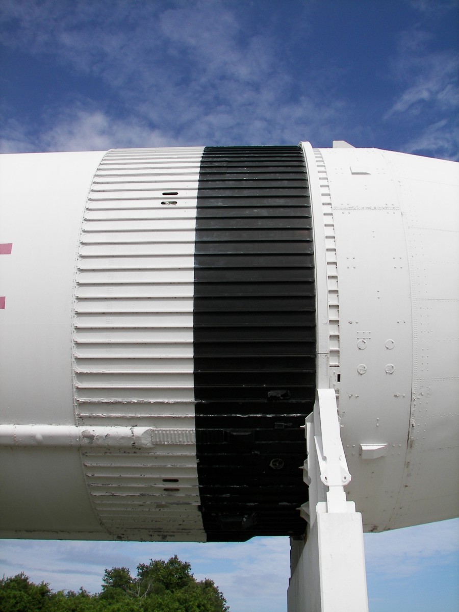
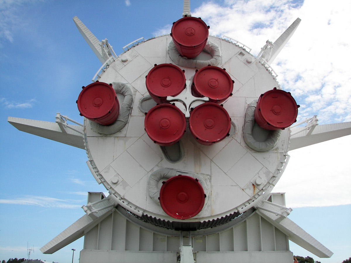
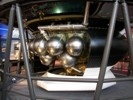
Saturn Instrument Unit (IU)
Part of all Saturn 5 rockets, the Instrument Unit included guidance equipment and computers for all three stages of the rocket.
Saturn 5 Instrument Unit
Saturn 5 Instrument Unit on display at the United States Space and Rocket Center. (Photos: Richard Kruse, 2008)
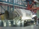
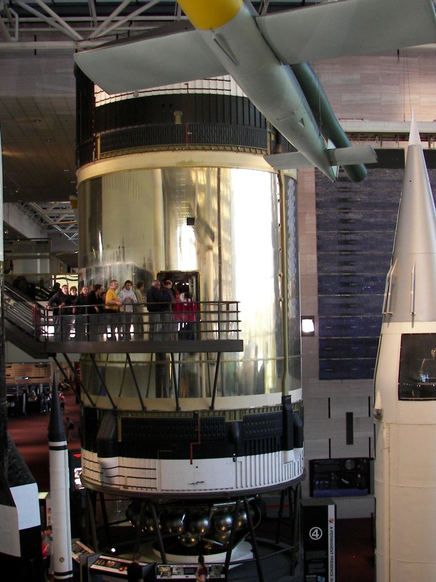
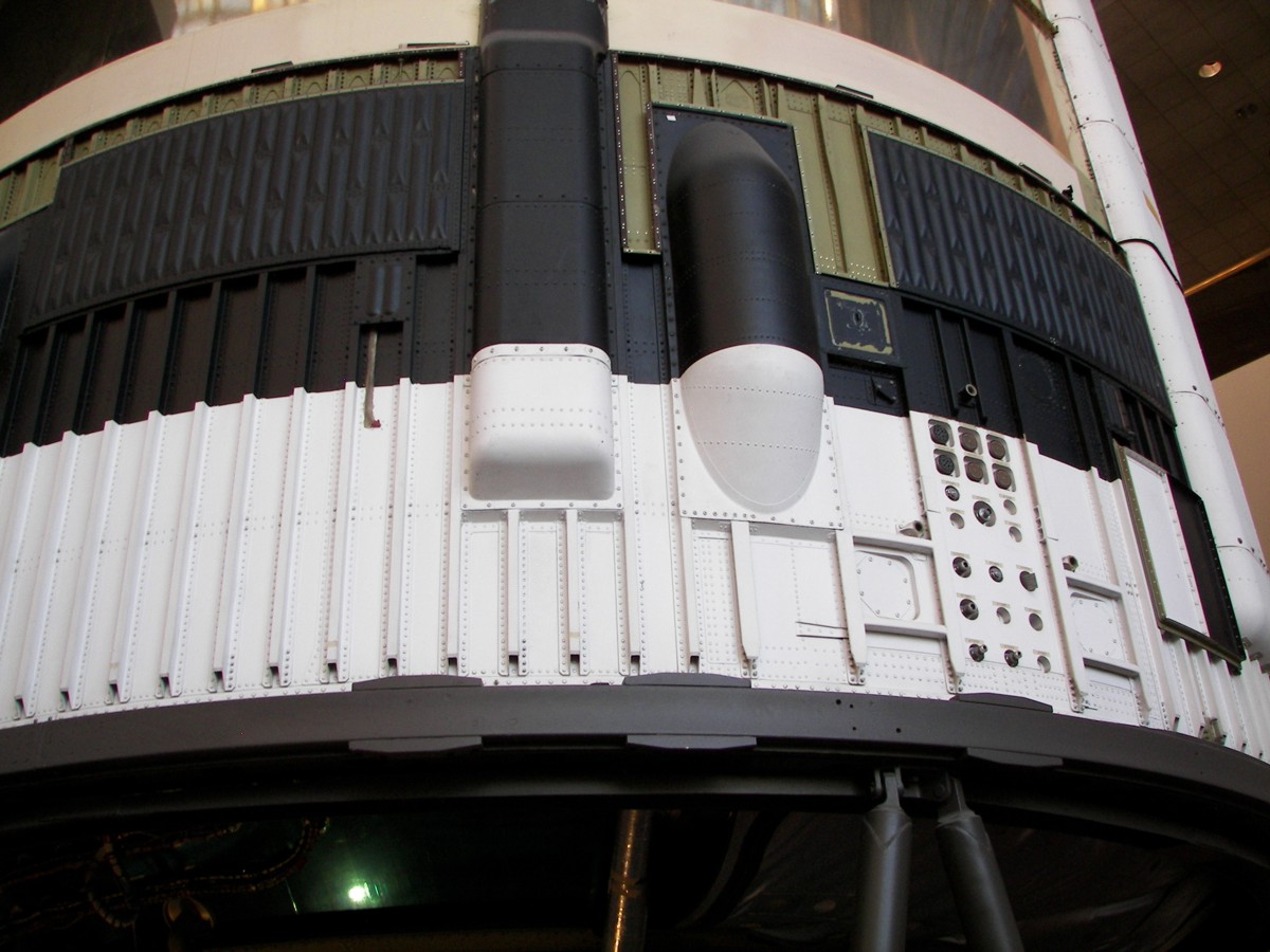
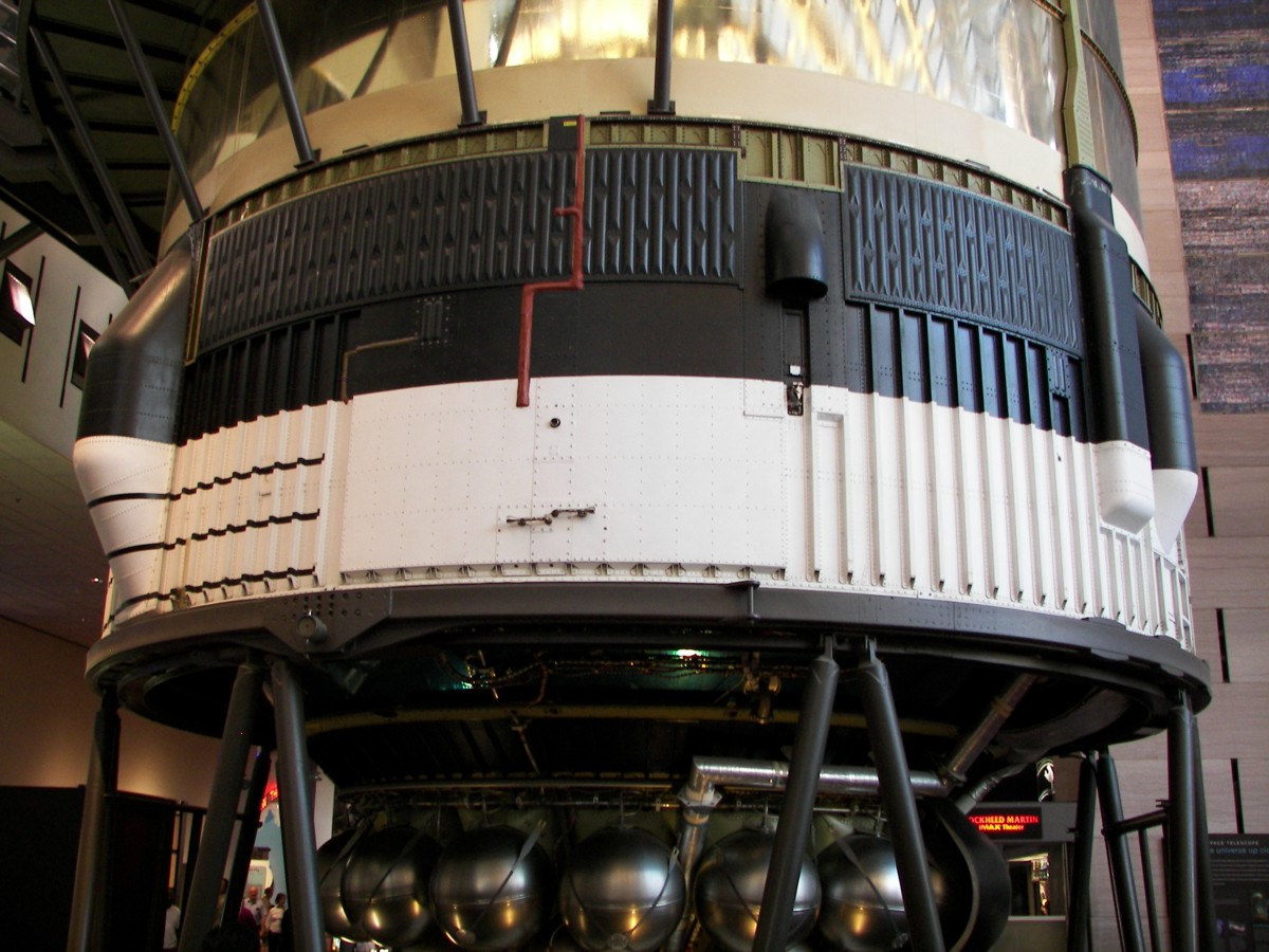
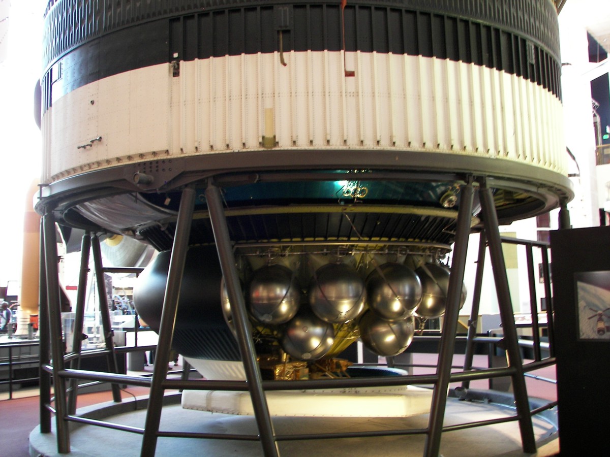
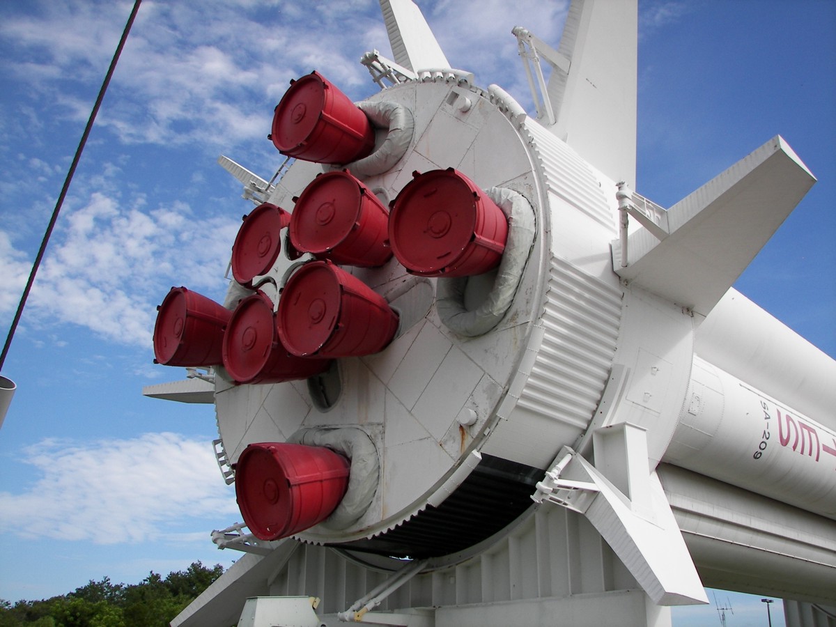
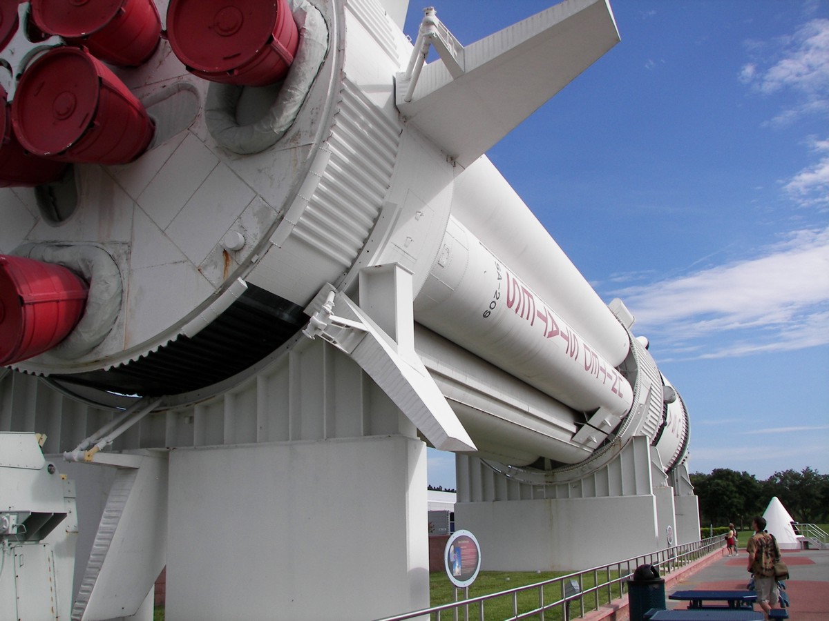
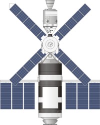
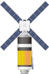
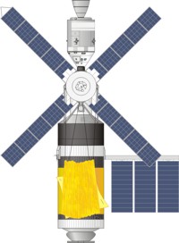
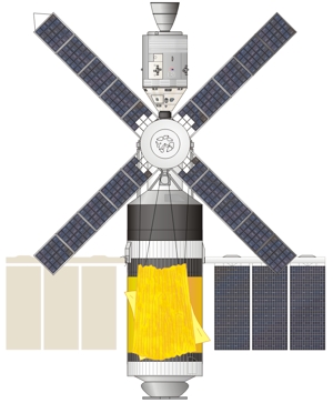
Orbital Workshop (OWS)
The largest component of the Skylab space station, the Orbital Workshop was built using a Saturn S-IVB rocket stage. The hydrogen fuel tank was outfitted as living quarters and work areas. The liquid oxygen tank was modified to serve as a waste tank.
The orbital workshop included laboratory space, a wardroom, a waste management compartment, and private sleeping compartments for the astronauts.
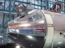
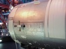
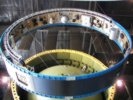
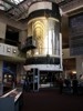
Skylab-B (Flight-Rated Backup)
Backup Skylab Orbital Laboratory on display at the National Air and Space Museum.(Photos: Richard Kruse, 2008)

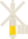
Parasol and Twin-Pole Sunshield
With the micrometeoroid shield stripped away at launch, sun light shined directly on the orbital workshop, resulting in significant temperature increases. Internal temperatures rose to over 100 degrees Fahrenheit.
Several sunshade systems were quickly designed and manufactured to help shade the station.
The first sunshade, known as the parasol, was deployed by the first Skylab crew on their second day in orbit. The sunshade was deployed through a scientific airlock on the side of the orbital workshop. The 22ft by 24ft parasol, composed of a woven nylon, mylar, and aluminum, reflected enough solar energy to lower the internal temperatures to tolerable levels.
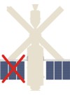
Another sunshade was deployed by the second Skylab crew. The twin-pole sunshield was assembled during a six hour spacewalk. The sunshield was supported by two long poles connected to a mounting bracket attached to the ATM structure. Each 55 foot long pole was composed of eleven, five foot long, interlocking pole sections. A 22ft x 24ft thermal shield, composed of painted aluminized mylar and woven orange nylon, was unfurled and stretched over the exposed area of the orbital workshop. Lines attached to the thermal shield were pulled taut and tied to outriggers on the ATM.
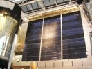
Solar Array System (SAS)
The Skylab orbital workshop was built with a pair of large solar arrays. The solar "wings" were designed to be folded against the side of the orbital workshop during launch. Once in orbit, the wings were to be deployed.
Shortly after liftoff, a micrometeoroid shield tore away from the station, resulting in significant damage to several systems. One solar wing was torn completely from the station. The other wing, jammed by debris, failed to deploy completely. Thanks to heroic efforts by the first Skylab crew, the remaining solar wing was successfully deployed.
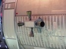
Skylab Solar Array
Backup Skylab Orbital Laboratory on display at the National Air and Space Museum.(Photos: Richard Kruse, 2008)

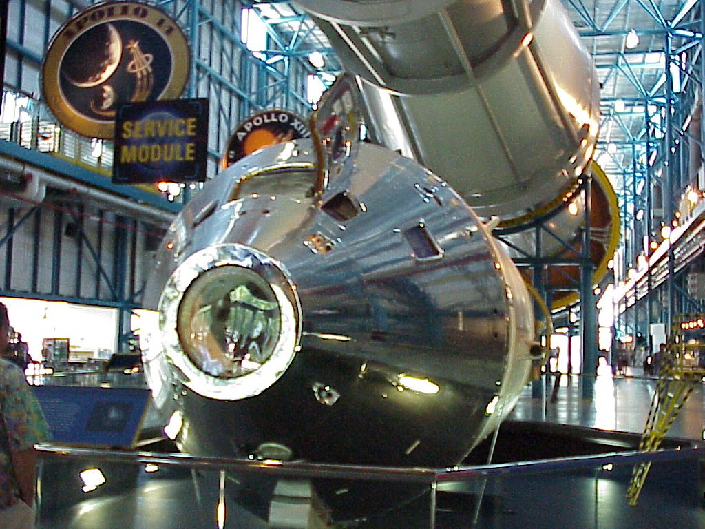
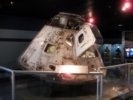
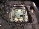
Apollo Command and Service Modules (CSM)
Apollo Command and service modules were used to ferry astronauts to the station. Three crewed missions were flown. A fourth Apollo spacecraft, CSM-119, was held in reserve for a possible rescue mission. The un-flown CSM-119 is currently on display in the Saturn 5 Center at Kennedy Space Center.
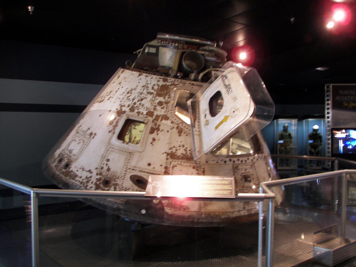
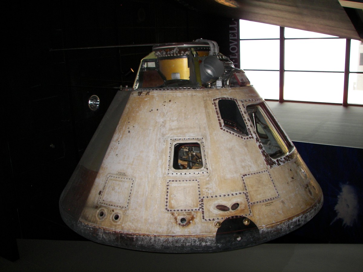
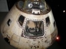
Skylab 2 (CM-116)
Skylab 2 Command Module on display at the National Museum of Naval Aviation. Launched on 25 May 1973, astronauts Charles Conrad (Commander), Paul Weitz (Pilot) and Joseph Kerwin (Science Pilot) spent 28 days in space. (Photos: Richard Kruse, 2007)
Skylab 3 (CM-117)
The Skylab 3 Command Module is on display at the Great Lakes Science Center in Cleveland, Ohio. Launched on 28 July 1973, astronauts Alan Bean (Commander), Jack Lousma (Pilot) and Owen Garriott (Science Pilot) spent 59 days in space.
No photos yet.
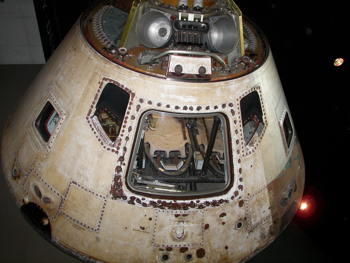
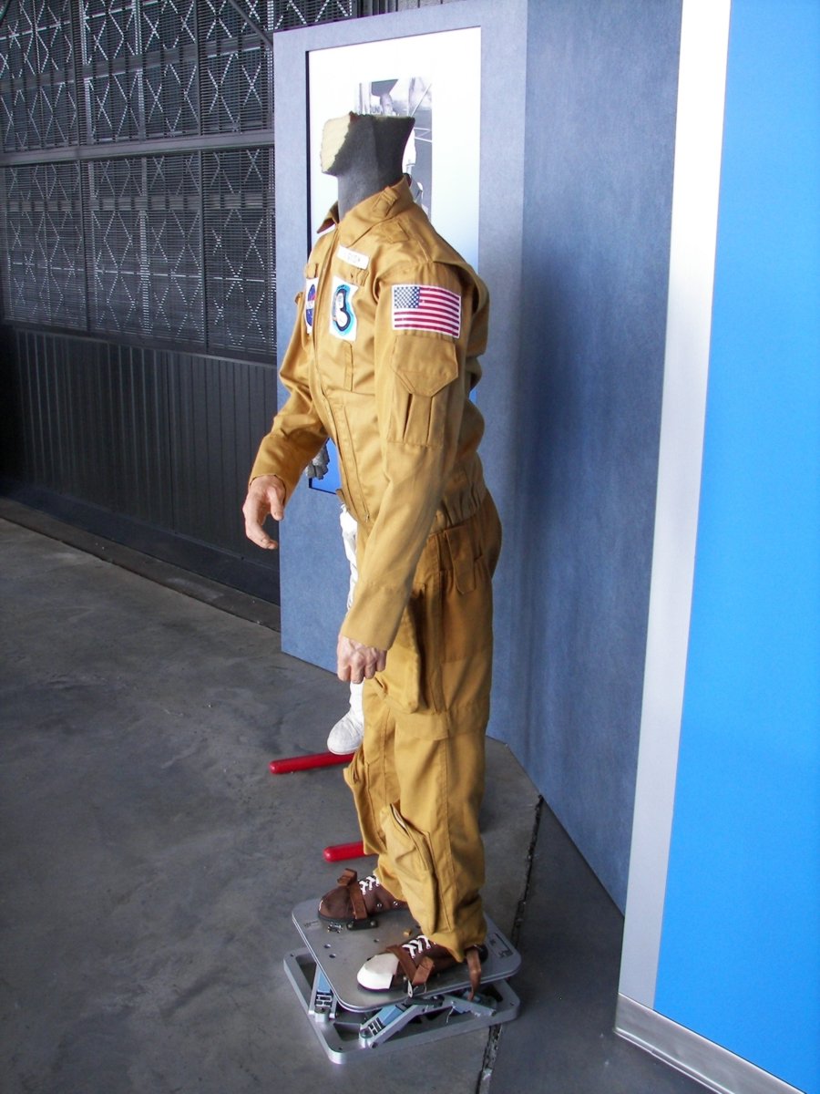
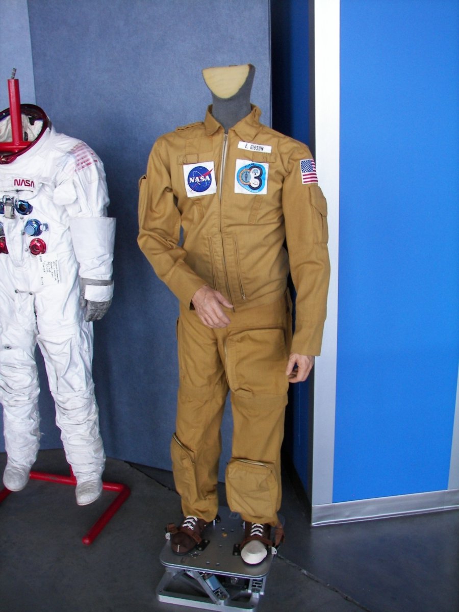
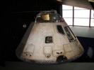
Skylab 4 (CM-118)
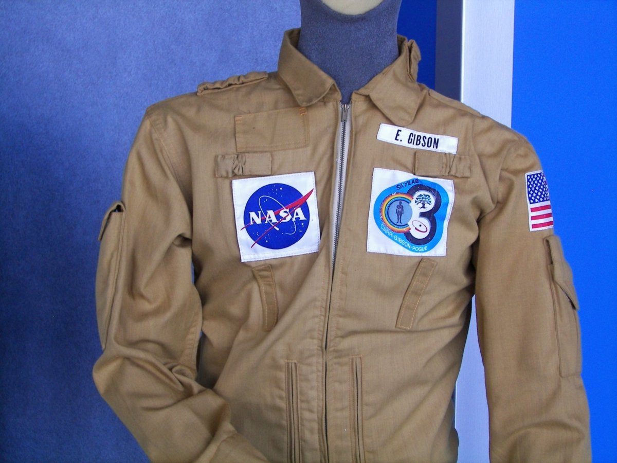
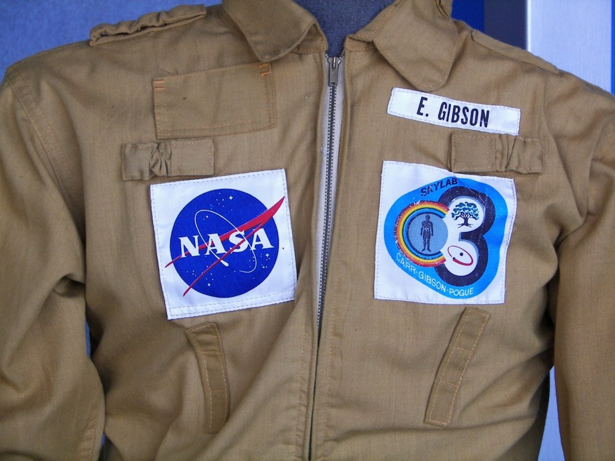
Skylab 4 Command Module on display at the National Air and Space Museum. Launched on 16 November 1973, astronauts Gerald Carr (Commander), William Pogue (Pilot) and Edward Gibson (Science Pilot) spent 84 days in space. (Photos: Richard Kruse, 2008)
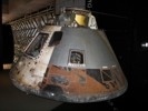
Apollo CSM-119
Apollo Command and Service Module on display in the Saturn 5 Center at Kennedy Space Center. CSM-119 served as the Skylab rescue vehicle and ASTP backup. (Photos: Kevin Reynolds, 2000)