Historic Spacecraft Lunar Module Illustration

Apollo Lunar Module

Apollo Lunar Module Illustration
Apollo Lunar Module

Lunar Module

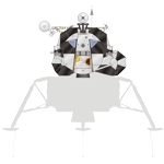
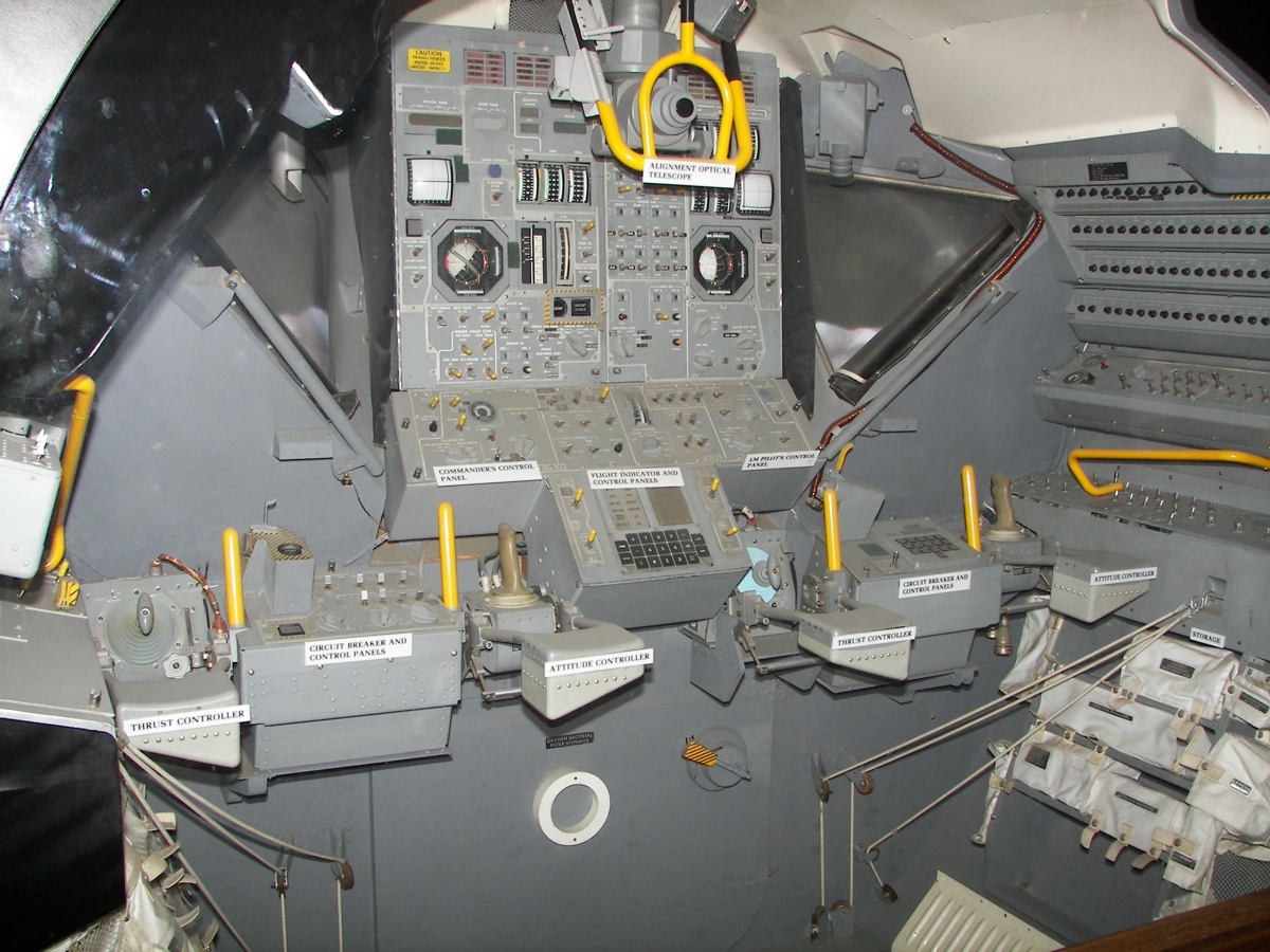
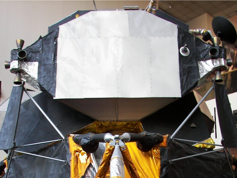
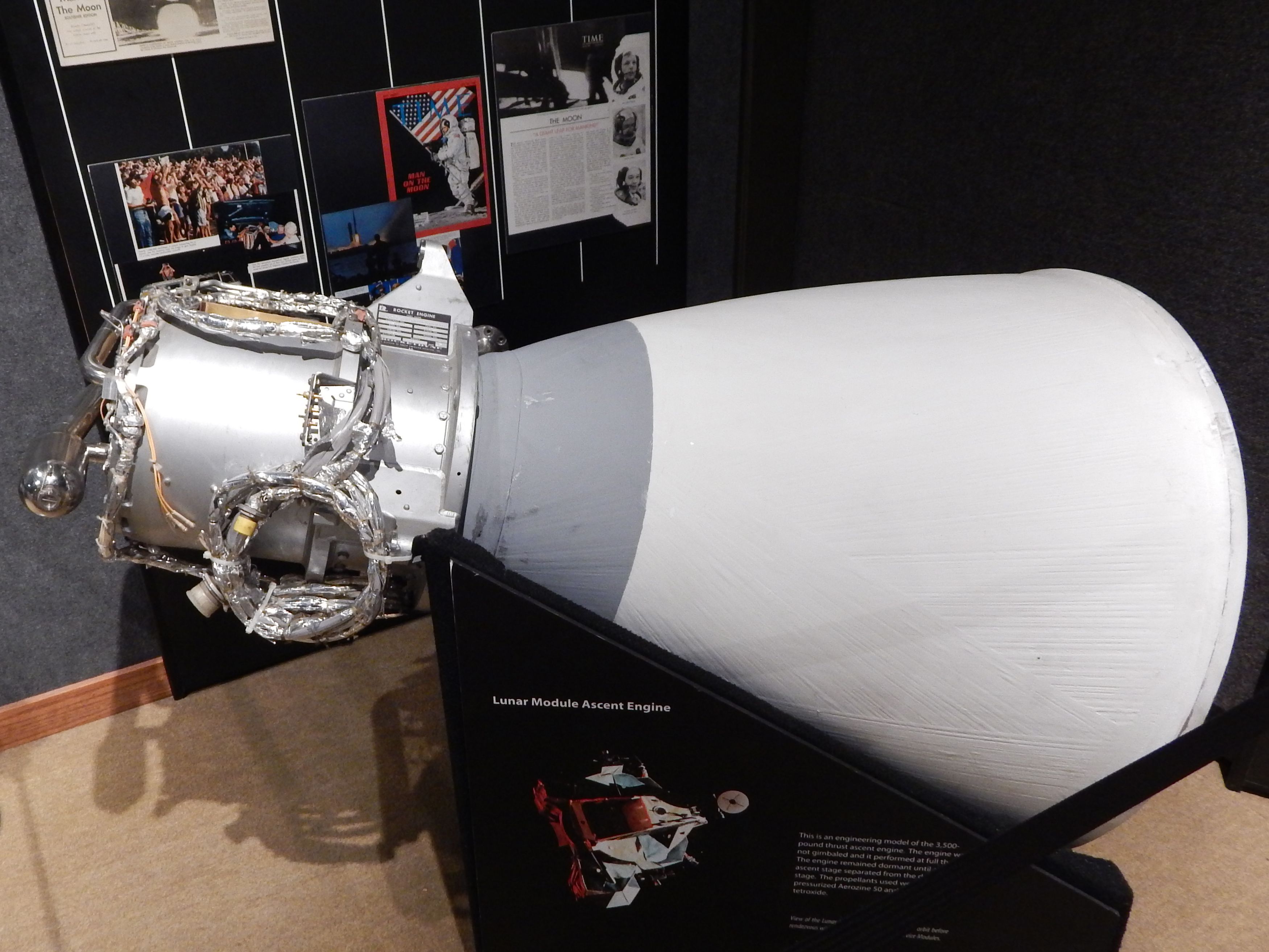
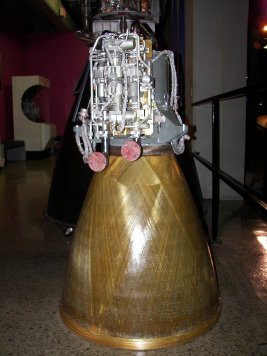
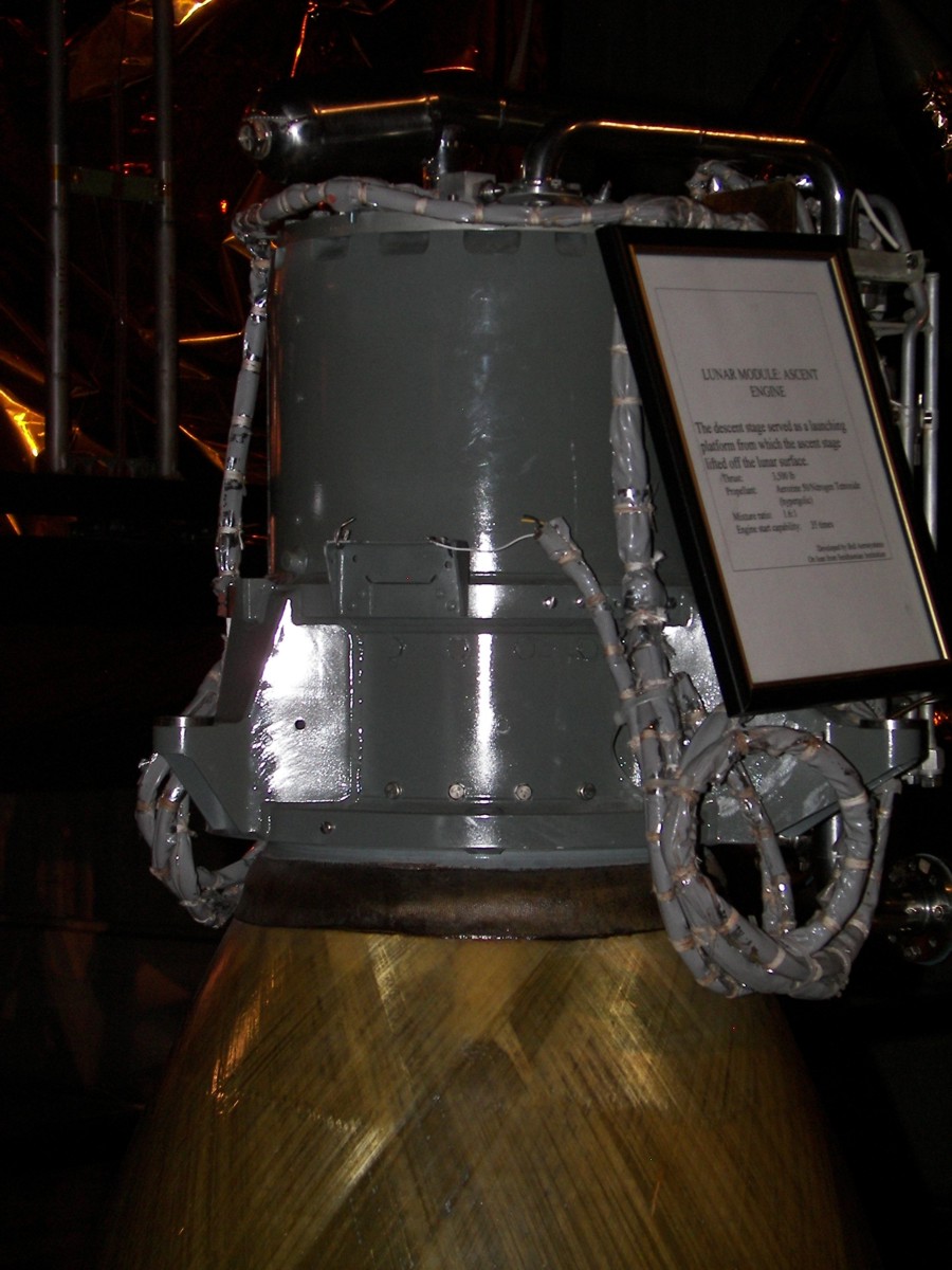
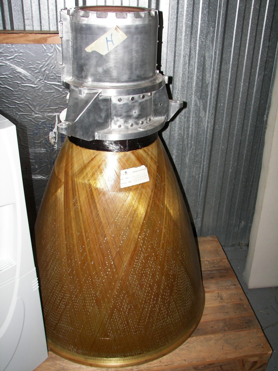
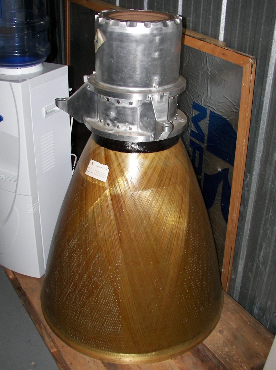
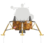
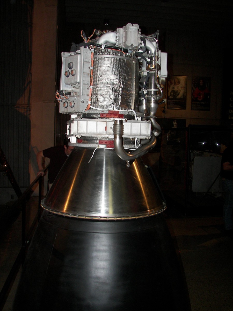
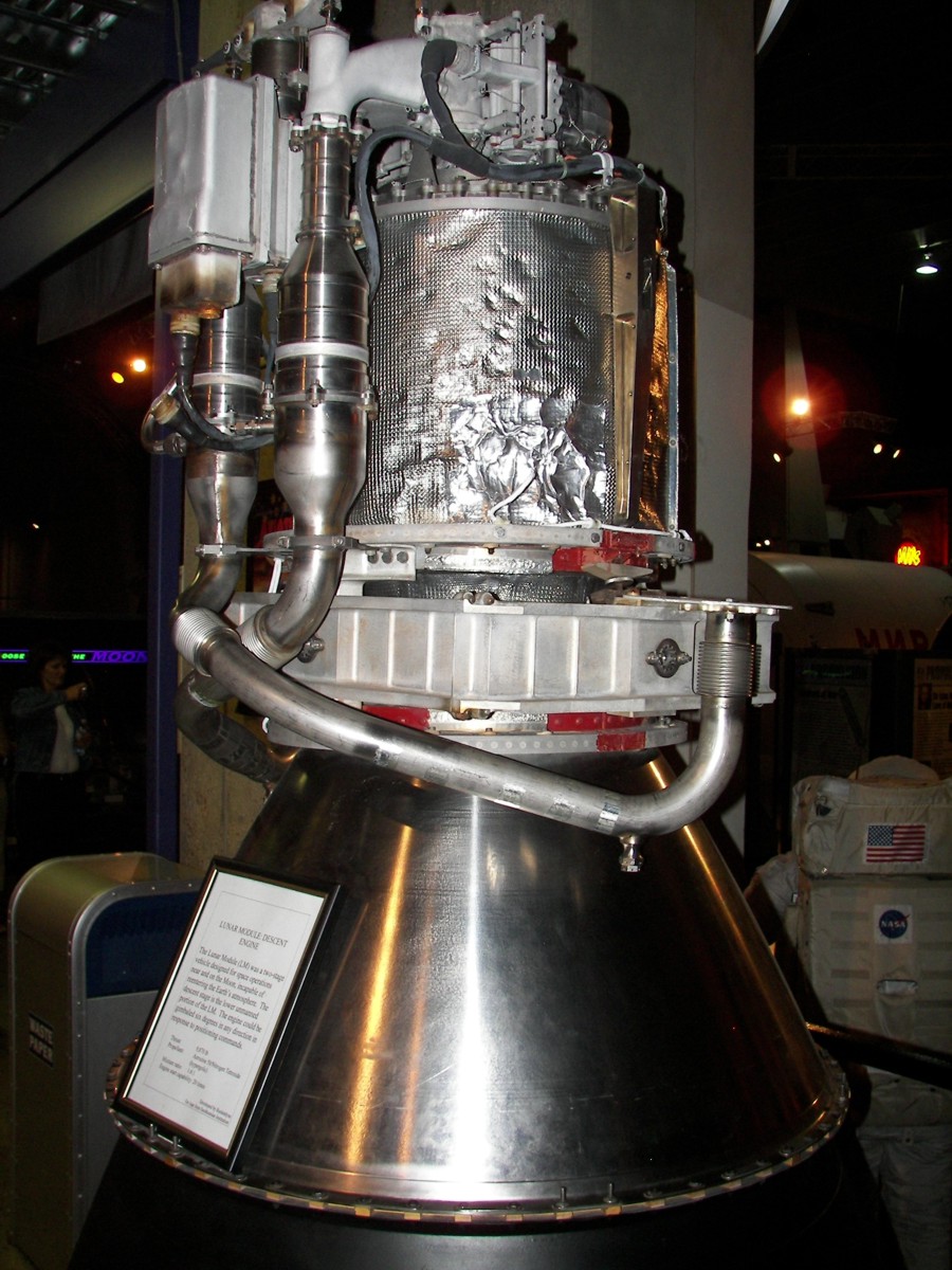
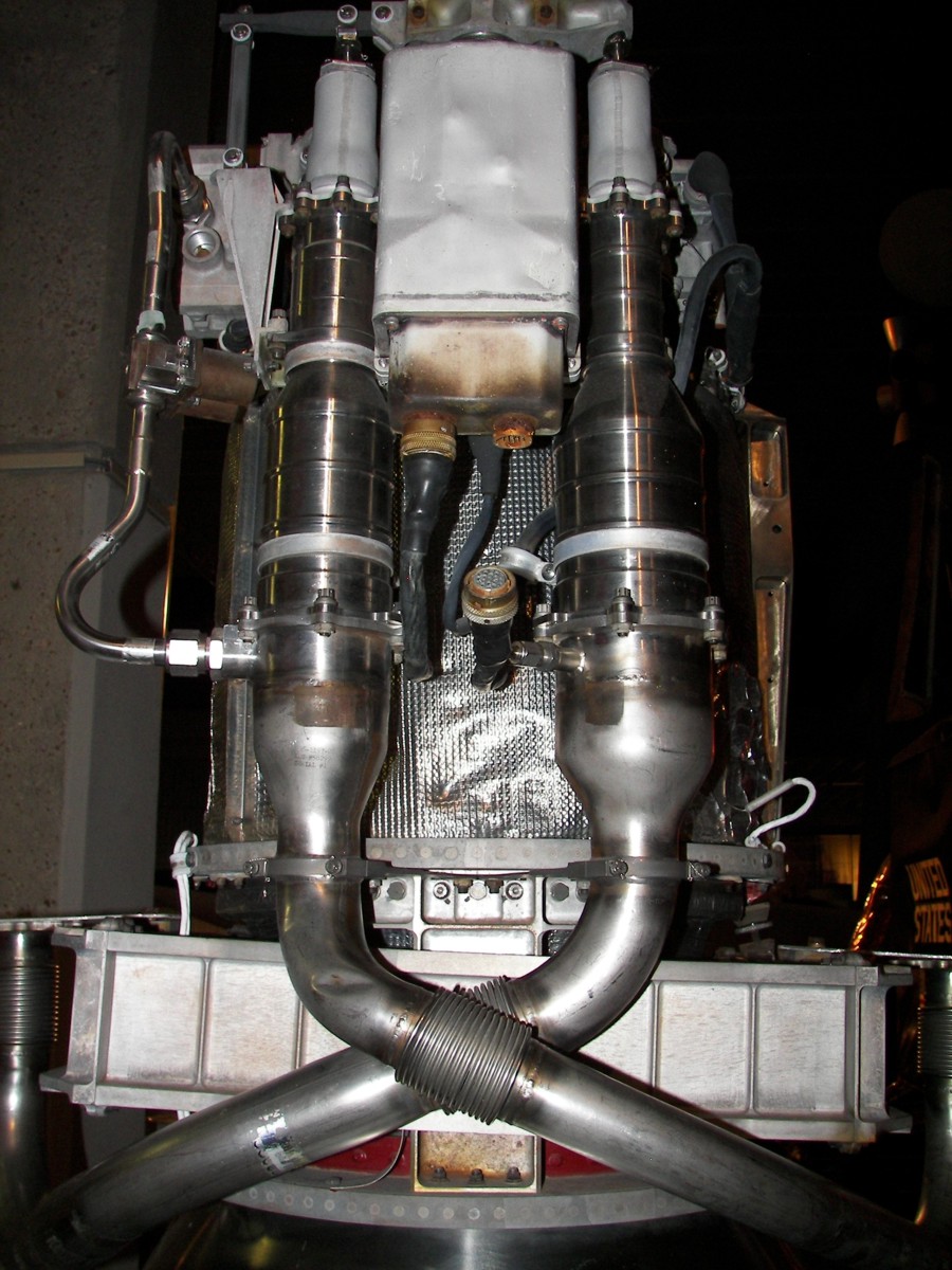
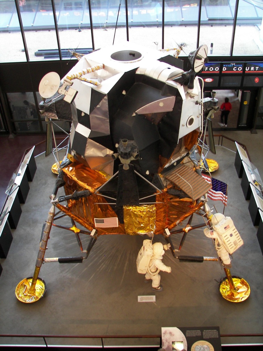
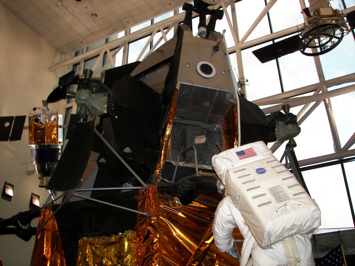
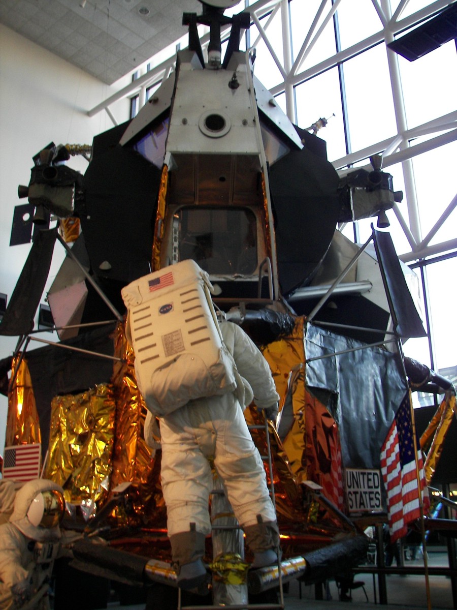
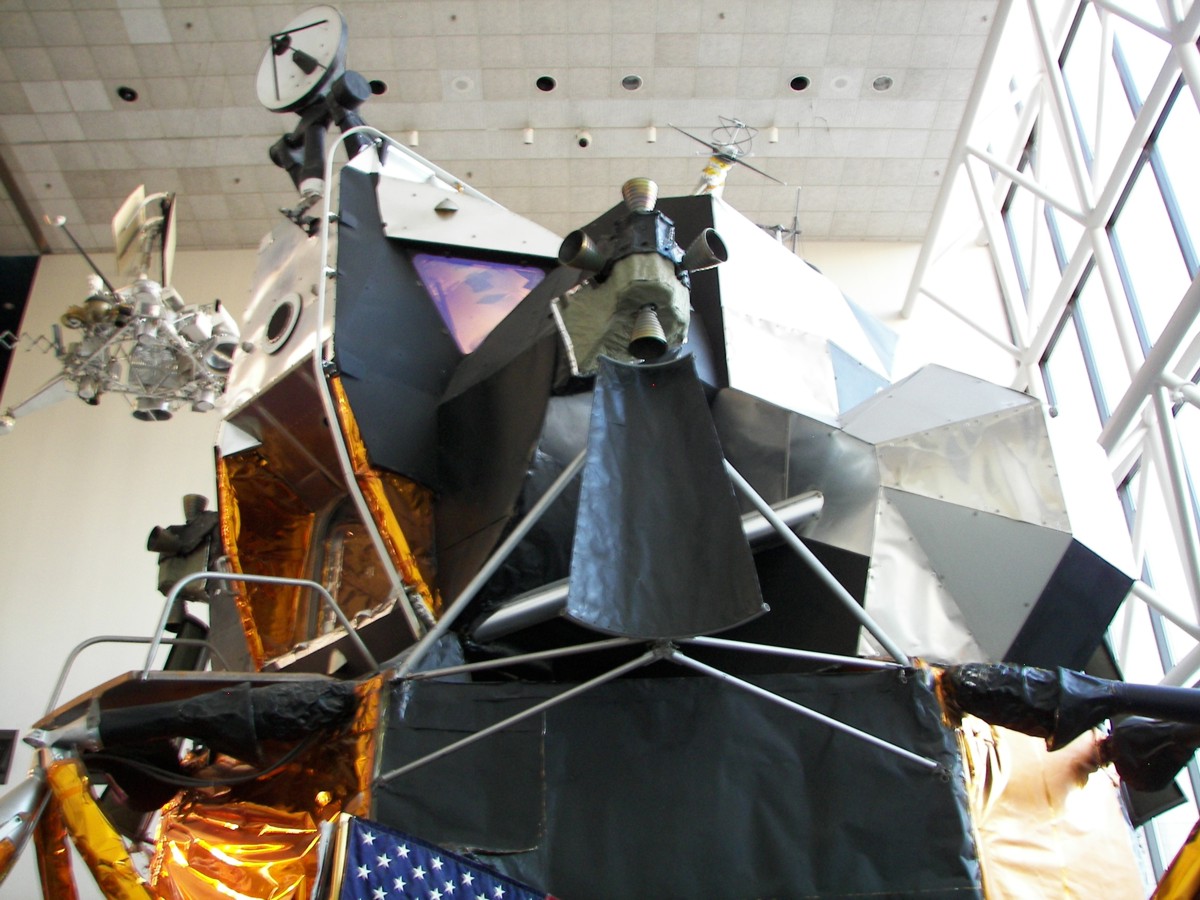
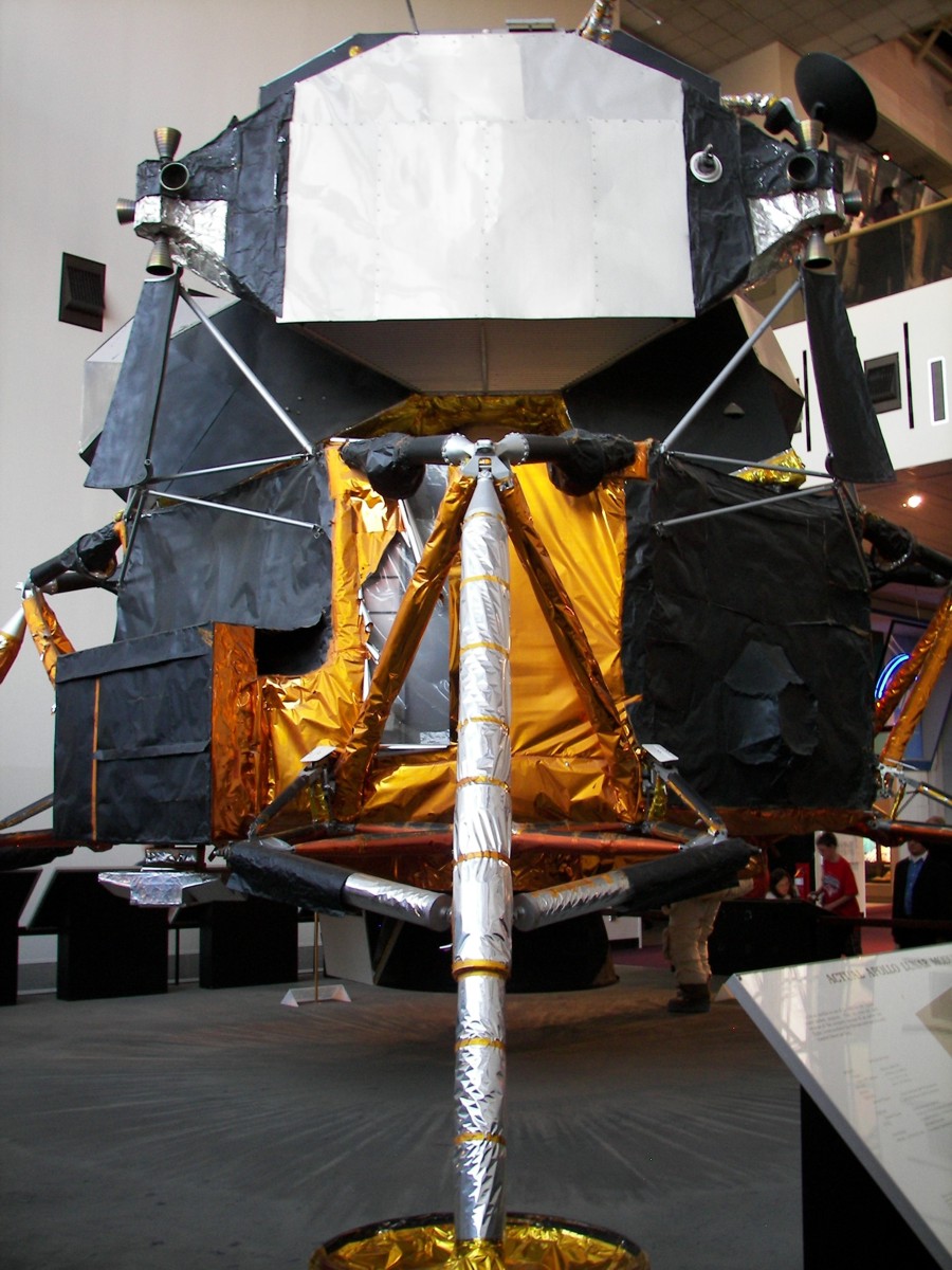
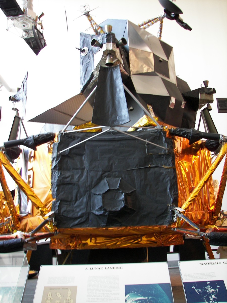
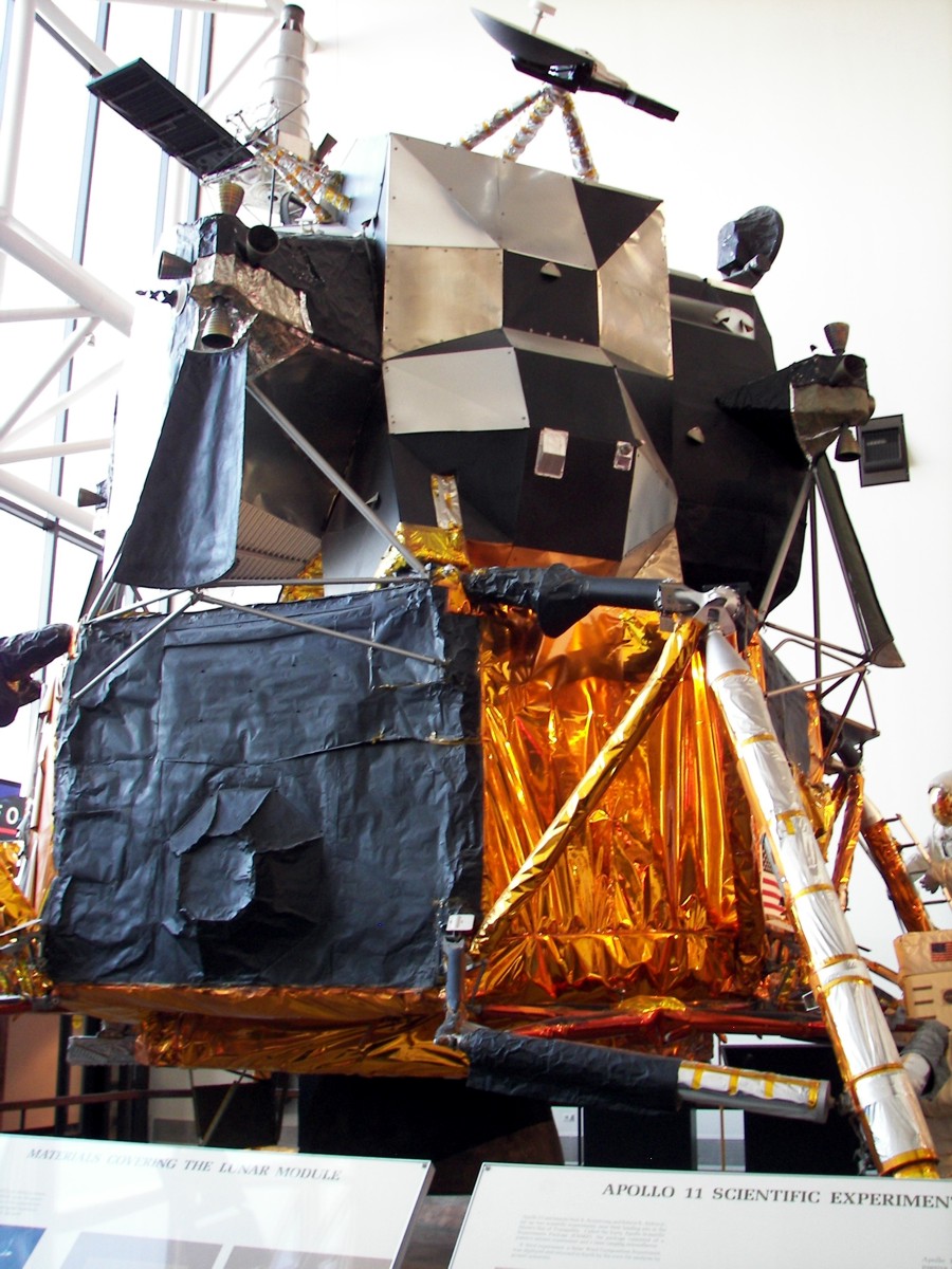
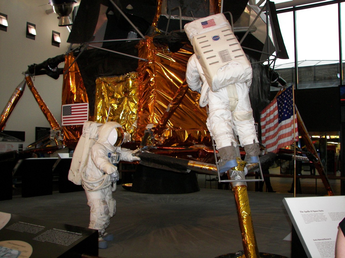
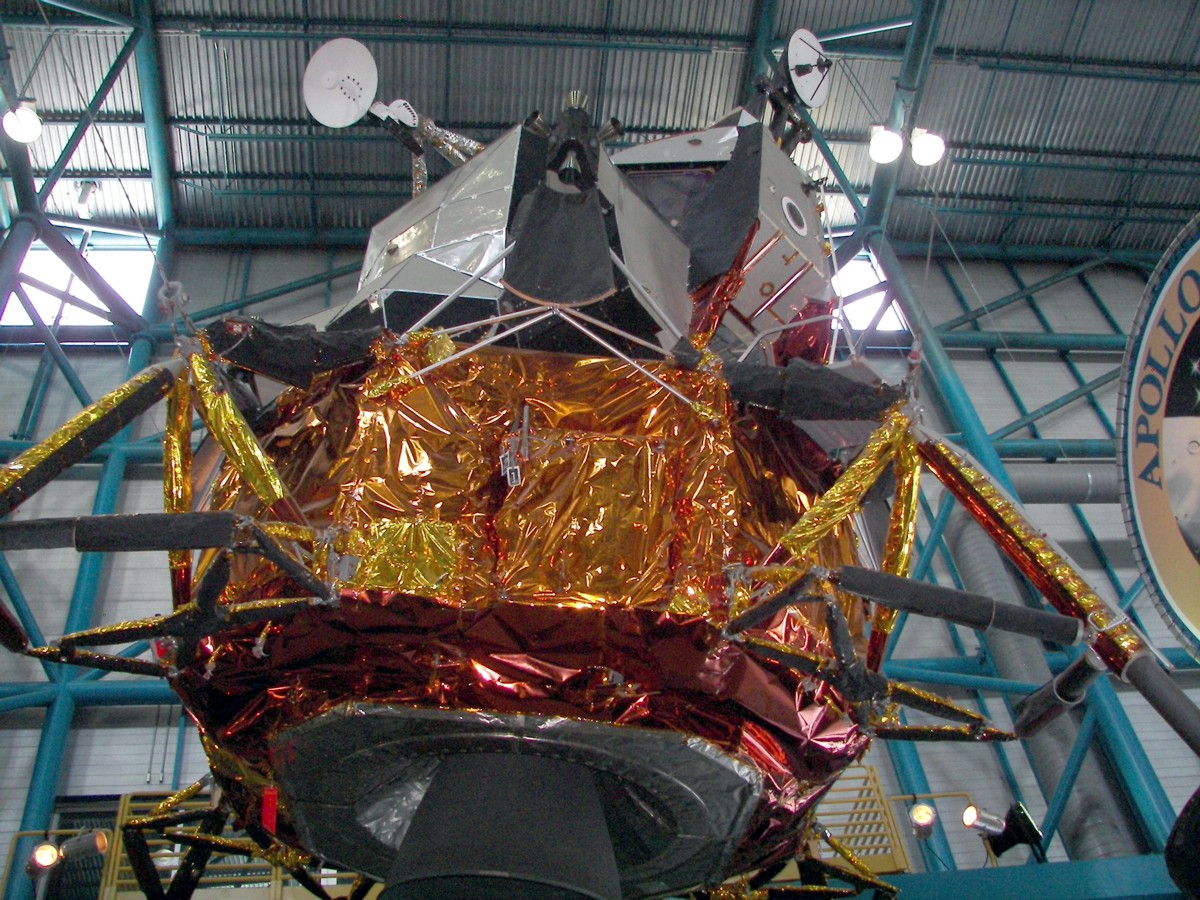
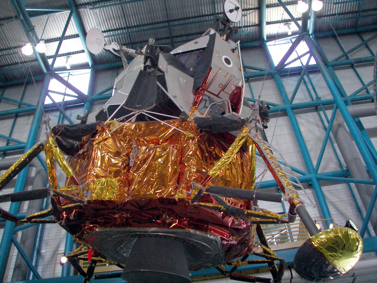
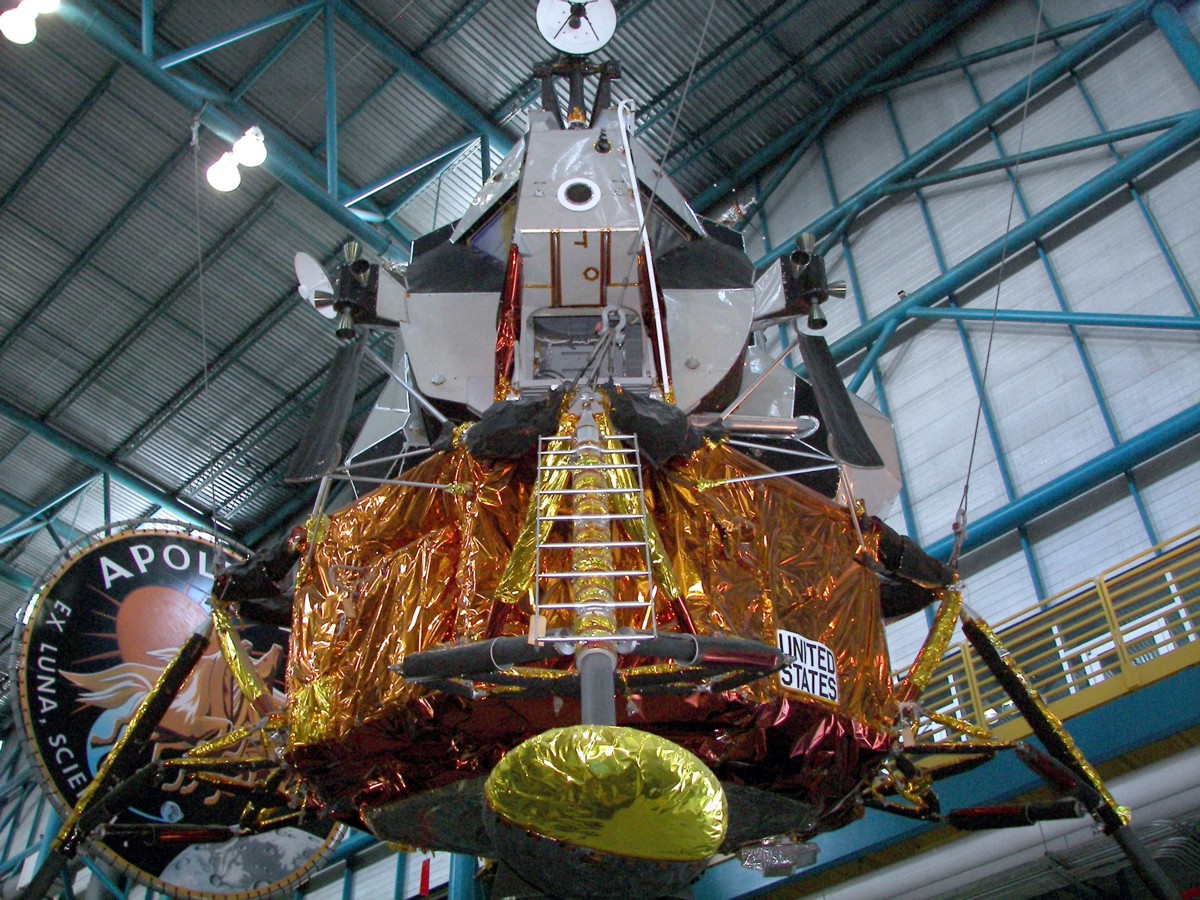
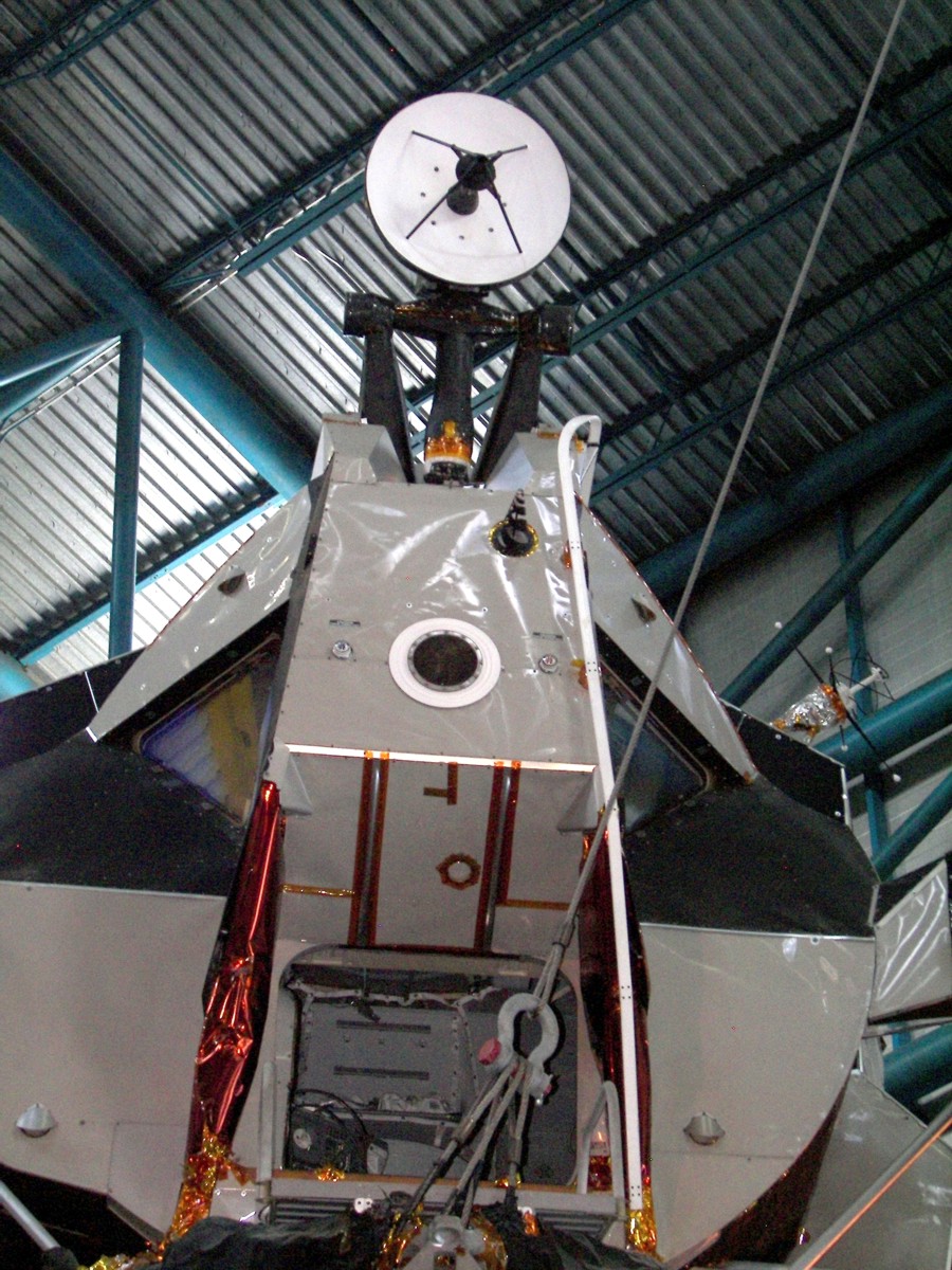
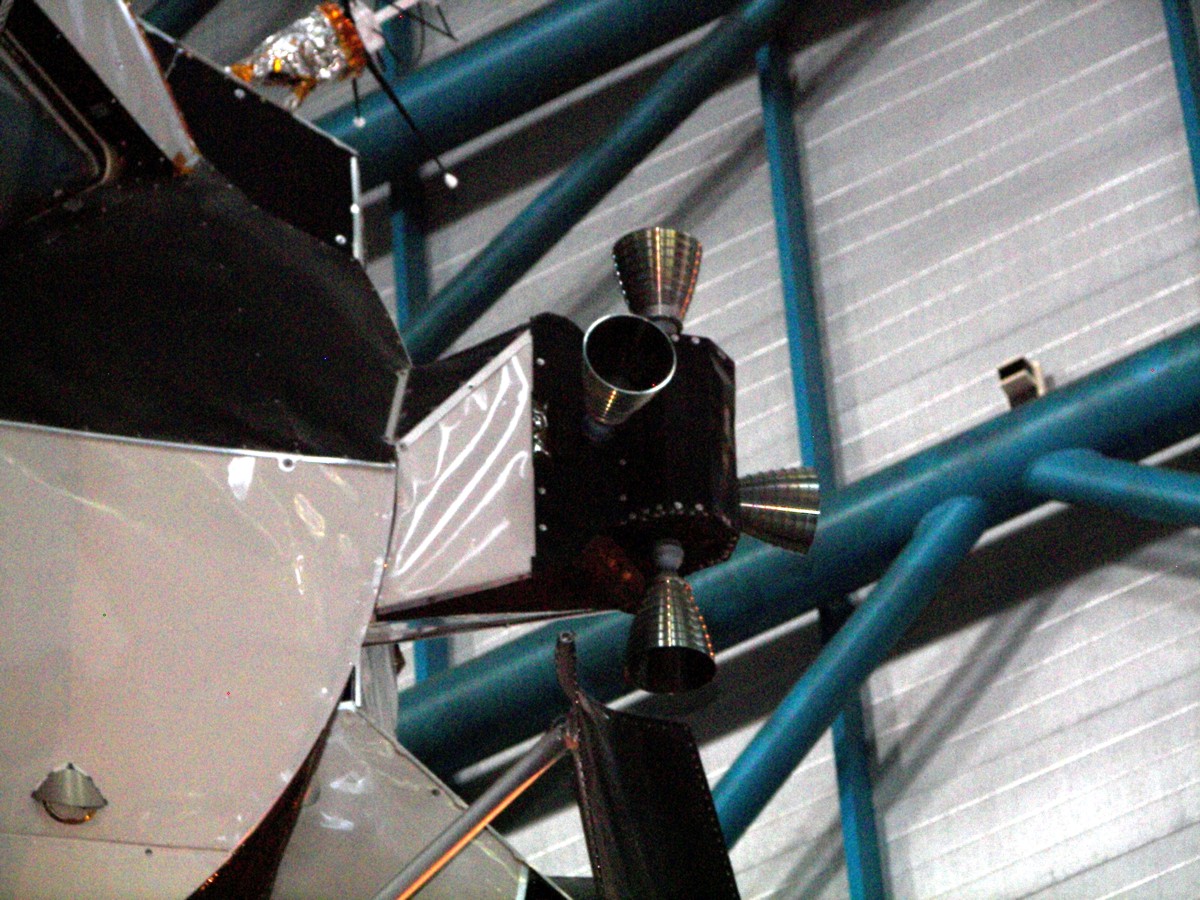
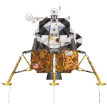
The Apollo Lunar Module (LM) was designed to transport two astronauts from Lunar orbit to the lunar surface and back again. Developed by Grumman, the LM had two stages. The lower component was known as the descent stage and the upper part was the ascent stage.

The first unmanned test flight of a Lunar Module occurred with the Apollo 5 (AS-204) mission. Launched on 22 January 1968, the mission was a success. Apollo 9 was the first mission to test the LM in Earth orbit with a crew onboard. The first test in Lunar orbit occurred with the Apollo 10 mission.

Apollo 11, launched on 16 July 1969, would be the first landing mission. LM-5, piloted by Neil Armstrong and Edwin Aldrin, landed successfully on the Lunar surface on 20 July 1969.

Apollo CSM and LM ascent stage Illustration
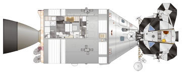
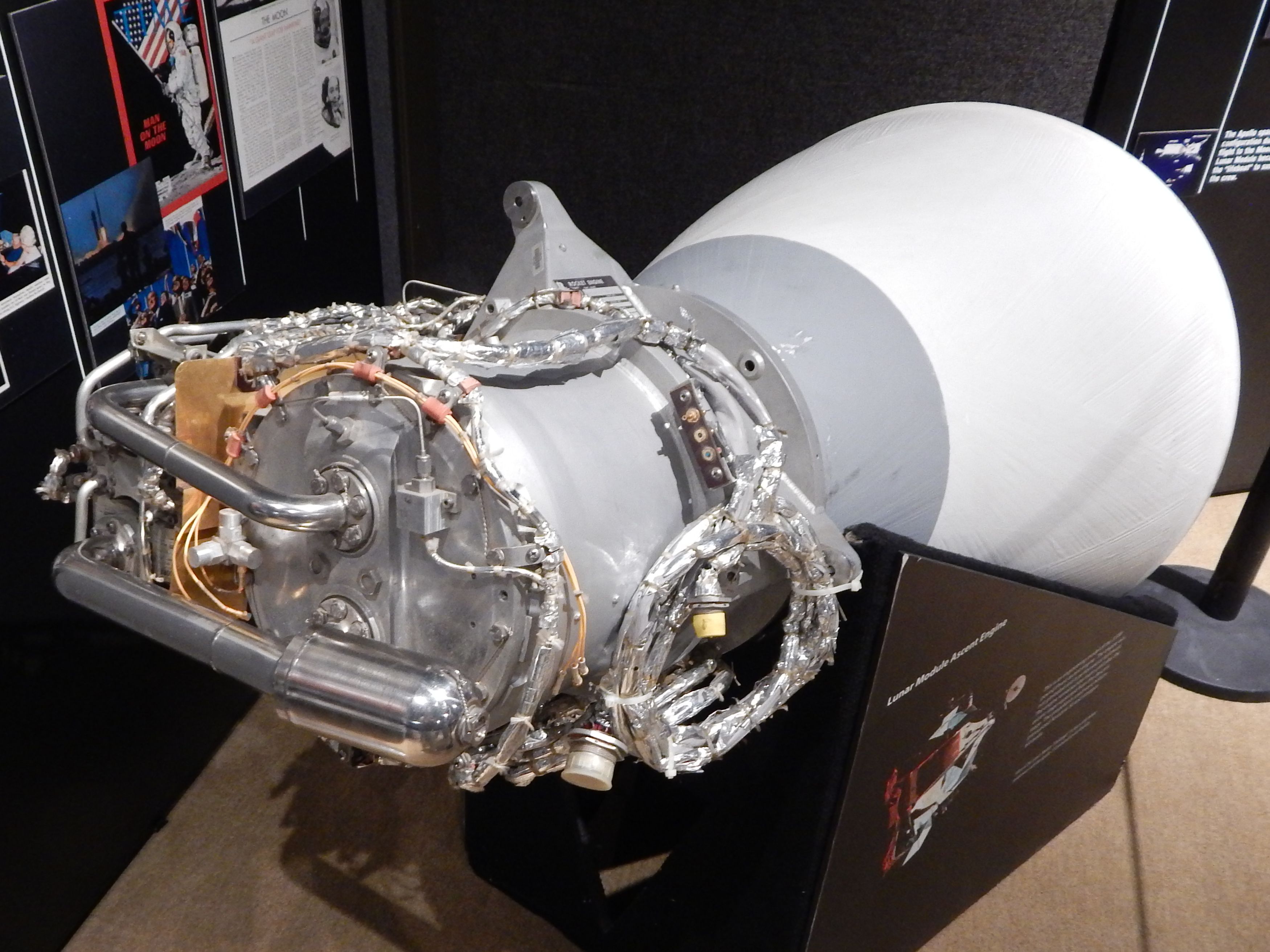
Apollo J-Class CSM and LM Ascent Stage

Improved Lunar modules, known as 'H' series models, were flown on Apollo 12, 13 and 14. These LMs could spend two days on the Lunar surface.

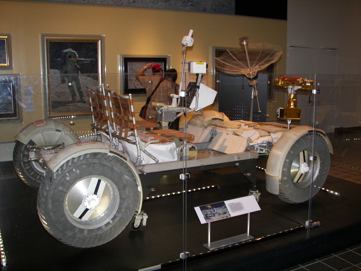
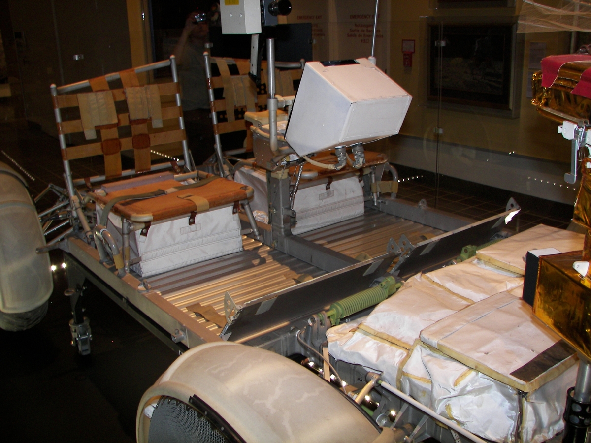
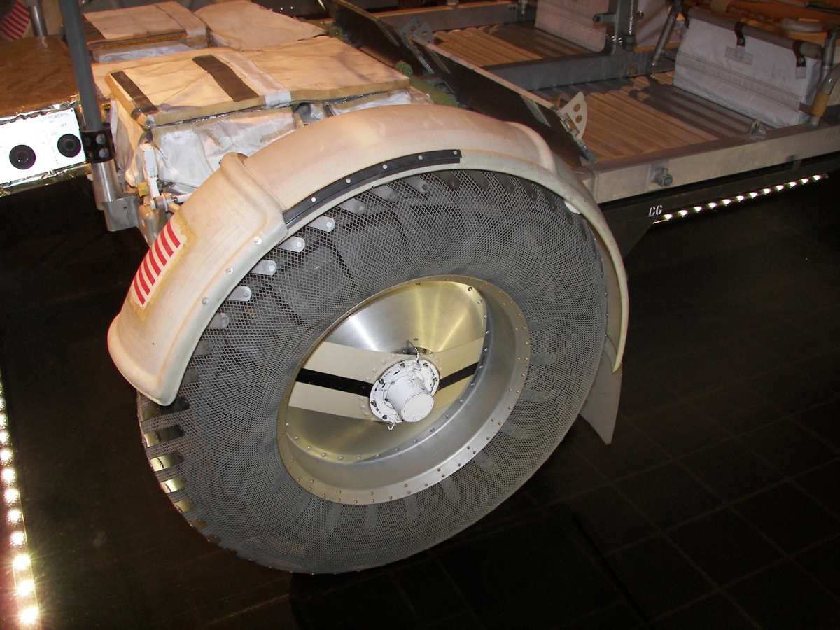
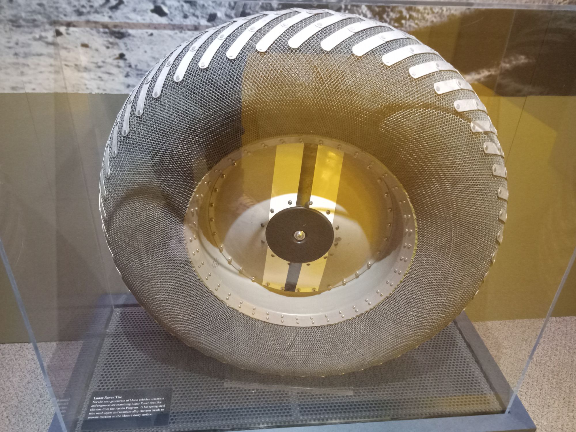
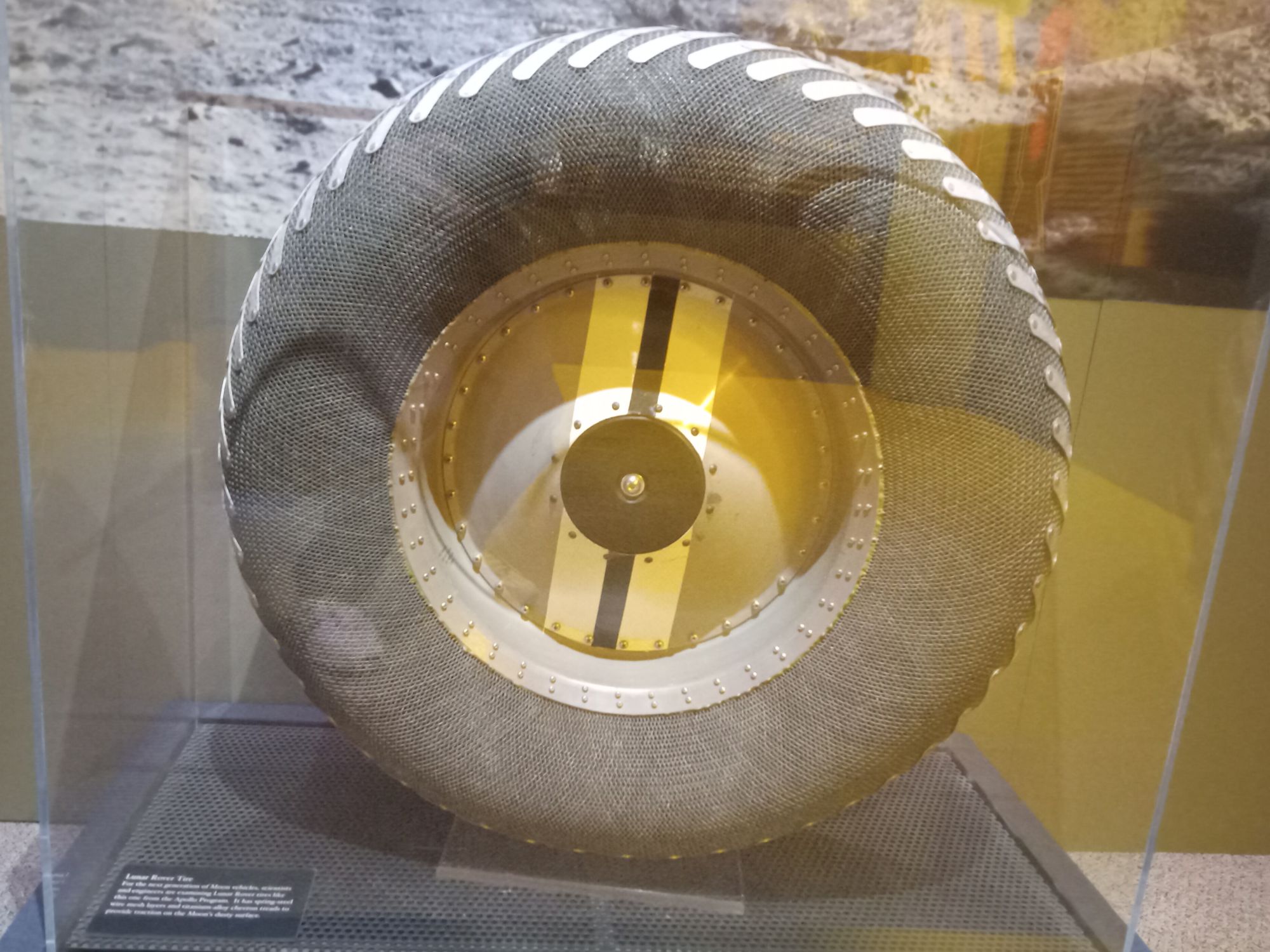
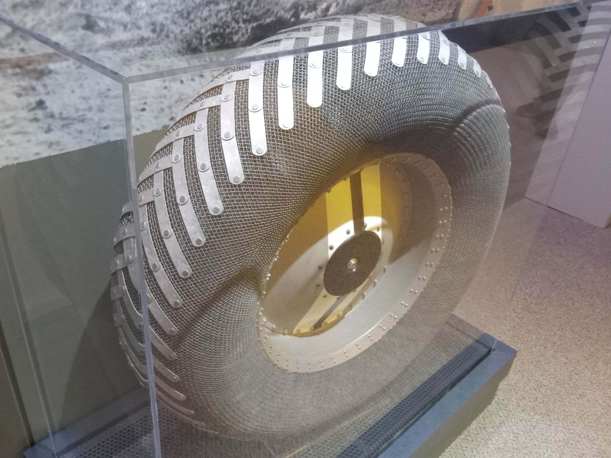
Later versions of the Lunar module, used on Apollo 15, 16 and 17, featured even more improvements. Known as 'J' series lunar modules, these spacecraft could stay on the surface for three days. The advanced landers also included room for a Lunar Roving Vehicle.

List of Lunar Modules
Serial
Number
MissionNameLaunch
Date
Mission
LM-1Apollo 5 --- 22JAN1968 Unmanned test in Earth orbit.
LM-2--- --- --- Not Flown. Currently on display at the National Air and Space Museum. (Photos)
LM-3Apollo 9 Spider 3MAR1969 Lunar module tested in Earth Orbit.
LM-4Apollo 10 Snoopy 18MAY1969 Lunar module tested in Lunar Orbit.
LM-5Apollo 11 Eagle 16JUL1969 Lunar landing at Mare Tranquillitatis.
LM-6Apollo 12 Intrepid 14NOV1969 Lunar landing at Oceanus Procellarum.
LM-7Apollo 13 Aquarius 11APR1970 Landing aborted.
LM-8Apollo 14 Antares 31JAN1971 Lunar landing at Fra Mauro.
LM-9--- --- --- Not Flown. Currently on display at Kennedy Space Center. (Photos)
LM-10Apollo 15Falcon 26JUL1971 Lunar landing at Hadley-Apennines.
LM-11Apollo 16Orion 16APR1972 Lunar landing at Descartes.
LM-12Apollo 17Challenger 7DEC1972 Lunar landing at Taurus-Littrow.
LM-13--- --- --- Not used.
LM-14--- --- --- Not used.
LM-15--- --- --- Not used.

Lunar Module Ascent Stage Illustration
Lunar Module Ascent Stage
LM Interior
Luner Module Interior on display at NASM.
(Enlarge)

Lunar Module Ascent Stage

Crew Compartment

The pressurized crew compartment dominated the front of the ascent stage and included flight stations for both the commander and pilot. The crew compartment also included environmental control system equipment, the ascent stage engine cover, and storage areas for equipment and supplies. A square hatch, located on the front of the pressurized compartment, allowed space suited astronauts to exit the spacecraft. A circular docking hatch, located on the top of the spacecraft, permitted docking with the Apollo command module.

Two large, triangular windows allowed easy viewing of the lunar surface. A rectangular window, located on the top of the spacecraft over the commanders flight station, was used during rendezvous and docking with the command module.

LM aft equipment bay
LM Aft Equipment Bay
(Enlarge)

Aft Equipment Bay

The Aft Equipment Bay, housing electronic components, was located on the rear of the spacecraft. The bay was unpressurized and included a water-glycol cooling system to prevent equipment from overheating. Two oxygen tanks and two helium tanks were located in the bay.

Reaction Control Subsystem

The Reaction Control Subsystem (RCS) was used to control attitude and translation of the Lunar Module. The system consisted of 16 thrusters arranged in clusters of four. The system used hypergolic propellants.

The RCS was made up of two independent systems each with eight thrusters. Each system included its own propellant supply and helium pressurization equipment.

During ascent from the Lunar surface, the RCS system could be configured to draw fuel from the main propulsion system fuel tanks. This preserved fuel in the RCS tanks for maneuvering in Lunar orbit.

LM RCS quad
LM RCS Cluster
(Enlarge)

Ascent Stage Engine

The ascent stage engine was used to launch from the lunar surface to lunar orbit. Designed to be as reliable as possible, the ascent engine produced a fixed thrust and cannot be gimbaled. The engine used hypergolic propellants.

Propellant was contained in two spherical tanks located on either side of the ascent stage. Helium was used to pressurize the system.

Apollo Lunar Module Ascent Engine Photos

The following photos were taken at the EAA Museum. (Photos: Richard Kruse, 2017)

Top of lunar module ascent engine. Lunar module ascent engine details. Side view of lunar module ascent engine. Lunar module ascent engine. Lunar module ascent engine bell.

Lunar Module Ascent Engine on display at the United States Space and Rocket Center

(Photos: Richard Kruse, 2007)

Apollo Lunar Module Ascent Engine Apollo Lunar Module Ascent Engine Apollo Lunar Module Ascent Engine Apollo Lunar Module Ascent Engine Apollo Lunar Module Ascent Engine Apollo Lunar Module Ascent Engine

Lunar Module Ascent Engine in Storage at the Michigan Space Science Center

(Photos: Richard Kruse, 2008)

Ascent Engine Lunar Module Ascent Engine
Lunar Module Descent Stage Illustration
Lunar Module Descent Stage

Lunar Module Descent Stage

Landing Gear

Four landing gear assemblies were attached to the descent stage. The landing gear were folded for launch and deployed later in the mission. A fixed outrigger assembly formed the top of each landing gear assembly. The outrigger assemblies also served as attachment points between the Lunar Module and the Saturn 5 SLA during launch.

The primary landing struts were of a piston-cylinder design. A crushable aluminum-honeycomb material, within the landing struts, was used to absorb landing loads. The top of each strut was attached to the outrigger assembly. A ball joint at the lower end of each strut attached to a circular footpad.

Other components of each landing gear assembly included secondary struts, a cross member assembly, side frames, and a deployment and down-lock mechanism.

A ladder and porch, mounted on the front leg, allowed astronauts access to and from the lunar surface. The ladder included nine rungs.

The remaining three legs each included an extendable lunar surface sensing probe. When a probe contacted the Lunar surface, an indicator light would alert the astronauts.

Descent Engine

The descent engine provided propulsion from Lunar orbit to the Lunar surface. The engine allowed the LM to hover over the Lunar surface as a landing site was selected. The throttleable engine used hypergolic propellants and could be gimbaled for thrust vector control.

Propellant was contained in four tanks located within the descent stage. Helium was used to pressurize the system.

Photos Lunar Module Descent Engine on display at the United States Space and Rocket Center

(Photos: Richard Kruse, 2007)

Apollo Lunar Module Decent Engine Apollo Lunar Module Decent Engine Apollo Lunar Module Decent Engine Apollo Lunar Module Decent Engine Apollo Lunar Module Decent Engine Apollo Lunar Module Decent Engine
Lunar Roving Vehicle Illustration
Lunar Roving Vehicle

Lunar Roving Vehicle (LRV)

The last three Apollo missions each included a lunar roving vehicle, or LRV, designed to transport two astronauts on traverses of up to several kilometers from the lander. For transport to the Moon, the rover was folded and packed into a quadrant of the Descent Stage.

The rover frame was 3.1 meters long and had a 2.3 meter wheelbase. Each wheel was powered by its own 1/4 hp motor. Two additional motors provided front and rear steering. A control panel and hand controller allowed either astronaut to operate the rover.

The rover communication system included both a low-gain antenna and a large mesh dish high-gain antenna. A color television camera, which could be remotely controlled from Earth, allowed scientists and engineers to monitor the astronauts progress.

At the end of the surface stay, an astronaut would park the rover a safe distance from the Lunar Module. Engineers in mission control could view television images of the ascent stage liftoff using the rovers TV camera.

List of Flown Lunar Roving Vehicles
RoverMissionCrewDistance
Covered
Longest
Drive
LRV-1Apollo 15 David Scott, Jim Irwin 27.8 km 12.5 km
LRV-2Apollo 16 John Young, Charles Duke 26.7 km 11.6 km
LRV-3Apollo 17 Gene Cernan, Harrison Schmitt 35.9 km 20.1 km

Photos of Apollo Lunar Rover

Lunar Roving Vehicle on display at the National Air and Space Museum in Washington DC. (Photos: Richard Kruse, 2009)

Apollo Lunar Rover Apollo Lunar Rover Apollo Lunar Rover Apollo Lunar Rover Apollo Lunar Rover Apollo Lunar Rover Apollo Lunar Rover

Lunar Module Photos

Lunar Module (LM-2)

Lunar Module (LM-2) on display at the National Air and Space Museum. This lunar module was to perform the second of two planned unmanned test missions. The mission was cancelled when the previous mission proved successful. (Photos: Richard Kruse, 2008)

Lunar Module Lunar Module Lunar Module Lunar Module Lunar Module Lunar Module Lunar Module Lunar Module Lunar Module Lunar Module Lunar Module Lunar Module Lunar Module

Lunar Module (LM-9)

Lunar Module (LM-9) on display at the Kennedy Space Center. This H-class lunar module was originally intended for Apollo 15. Apollo 15 eventually flew with LM-10, a much more capable J-class lunar module. (Photos: Richard Kruse, 2009)

Lunar Module 9 at KSC Lunar Module 9 at KSC Lunar Module 9 at KSC Lunar Module 9 at KSC Lunar Module 9 at KSC Lunar Module 9 at KSC Lunar Module 9 at KSC

References

Boeing Company, LRV Systems Engineering, Lunar Roving Vehicle Operations Handbook, Huntsville, Alabama. April 19, 1971.

Grumman Aerospace Corporation, Apollo Lunar Module News Reference, Bethpage, New York, In cooperation with NASA, 1968.

Grumman Aerospace Corporation, Apollo Operations Handbook - Lunar Module - LM 10 and Subsequent, Bethpage, New York, Prepared under direction of NASA, 1971.

Courtney G. Brooks, James M. Grimwood and Loyd S. Swenson Jr., Chariots for Apollo: A History of Manned Lunar Spacecraft, NASA SP-4205, Washington, D.C., 1979.

E. Cortright, ed. Apollo Expeditions to the Moon, NASA SP-350, Washington, D.C., 1975.

Creative Commons License Images by Richard Kruse are licensed under a Creative Commons Attribution-Noncommercial 3.0 United States License.

Historic Spacecraft Store